background image

MASTERSPLIT WP30

63

11

11

12

12

1

2

2

3

4

5

6

7

8

9

10

9

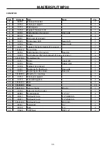
Part

Order no

Item

Note

Pcs.

1

30501

Beam

1

2

30502

Lifter arms

Extra equipment

2

3

30503

Lifters midbeam

Extra equipment

1

4

55307060

Hook

Extra equipment

1

5

30505

Lock

1

6

30507

Feed table support

1

7

55306640

Roll

1

8

30303

Frame of support roller

1

9

55307260

Flange bearing

2

10

30304

Supportroller

1

11

90035

Pin

5 mm

2

12

90039

Washer

50x62x3.0

6

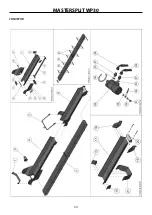
SHAFT AND LOADERS, EXTRA EQUIPMENT 

Содержание Mastersplit WP30

Страница 1: ...RSPLIT WP30 OPERATING MAINTENANCE AND SPARE PARTS MANUAL PLEASE READ THIS OPERATING AND MAINTENANCE MANUAL CAREFULLY BEFORE OP ERATING THE MACHINE STARTING FROM THE SERIAL NO 10420 THIS MACHINE MAY BE OPERATED ONLY BY ONE PERSON AT THE TIME MORE THAN ONE PERSON WORKING SIMULTANEOUSLY IS STRICTLY FORBIDDEN 45302100 B EN 131211 NKU ...

Страница 2: ...HINE OPERATION 20 ADJUSTMENT OF THE LENGTH OF SPLIT WOOD 20 ADJUSTMENT OF THE SPLITTING BLADE HEIGHT 21 CONVEYOR OPERATION ADJUSTMENT 21 CONVEYOR BELT ADJUSTMENT 22 WORKING WITH THE SPLITTING MACHINE 22 CHECK UPS AND PROCEDURES BEFORE THE STARTING OF THE OPERATIONS 23 STARTING THE COMBUSTION ENGINE Mastersplit PM 23 WORKING METHOD 23 PREPARING THE MACHINE FOR HAULING 25 DRIVING ON PUBLIC ROADS 28 ...

Страница 3: ...it WP30 Mastersplit WP36 type Serial No comply with machinery directive 2006 42 EEC Furthermore models with electric motors comply with Low Voltage Directive LVD 2006 95 EC and models with internal combustion engine comply with EMC directive 2004 108 EC regarding electromagnetic compliance Iisalmi 13 12 2011 place time Juha Hallivuori WARRANTY FOR THE MACHINE ISSUED BY THE MANUFACTURER ...

Страница 4: ... the manufacturer Contact details may be found in the WARRANTY sec tion THE USE OF THE MACHINE AND THE OPERATING RULE MASTERSPLIT WP36 is a semi automatic wood split ting machine which may be used for cutting and split tingpre adjustedlengthsofstems logging and sawing remnant clean construction timber waste etc The wood to be split is lifted on a feed table which will places the wood in the chains...

Страница 5: ...rsplit splitting machines can be equipped with a splitting blade cross blade for splitting the wood into four or six parts Mastersplit splitting machines can also be equipped with an additional wood splitter which safely can split even larger stems or already split wood into smaller pieces with ease When using the additional wood splitter the stem diameter should be max 40 cm whe reas the wood len...

Страница 6: ...ment lever D Wood loaders optional 5 Moving feed table E Shaft 6 Support legs 4 pcs F Conveyor 7 Additional wood splitter G Mobile transportation base for public roads extra equipment MODELS PROPULSION TR Tractor SM Electric motor PM Internal combustion engine SM TR Electric motor or tractor PM TR Internal combustion engine or tractor SPLITTING MACHINE MODELS ...

Страница 7: ...that the operating lever is on the 0 position Do not leave a running machine unattended Ensure that the machine cannot move from its position during the operation During operati on the machine must be mounted to a tractor The Mastersplit mobile transportation base must be prevented from moving during operation by using wheel chocks or taking other measures The machine must not used by a person who...

Страница 8: ...R CONVEYOR When adjusting the conveyor belt ensure that the engine is off Mastersplit TR SM PM and the power transmission has been switched off ensu ring that the tractor is unable to switch itself on or move Mastersplit TR The conveyor belt is adju sted so that it does not slide on the driving roller NOTE When removing wood remnants dirt or the like from the conveyor make sure the machine is at a...

Страница 9: ...e and repair If several operators use the machine each one must read the user manual carefully before operating the machine Label No 2 When operating the machine gloves hearing and eye protectors must be worn Label No 3 The label warns against a rotating blade 2 pcs LABELS ON THE SPLITTING MACHINE Make sure labels are not damaged and are always vi sible If labels must be replaced please contact yo...

Страница 10: ...imum rotation speed for the universal shaft Mastersplit TR Label No 6 Operating lever label Label No 7 Machine plate Label No 9 Mastersplit has been designed for the operation by one person only Label No 8 The label warns against movable machine parts ...

Страница 11: ...isk of crushing between the driving roller of the conveyor and the conveyor belt 2 pcs Label No 13 The label warns against the risk of crushing between the driving roller of the conveyor and the machine frame 2 pcs Label No 14 The label informs on the mounting position of the winch on the shaft and on the loaders for mounting the machine in its working position and dismounting it Label No 15 The l...

Страница 12: ...pecific instructions to start operating 1 Lift the machine on a solid and level surface If re quired adjust the machine into the horizontal posi tion by using the support legs 3 Loosen the strap 2 Turn the feed table extension into the horizontal position 4 Remove the strap form the conveyor ...

Страница 13: ...Carefully lower the shaft and make sure it is held by the strap 6 Loosen the shaft lock 8 Use the winch to lower the shaft down to the lo west position and make sure the strap does not fray If the machine is equipped with the wood loader extra equipment swivel the loader s hook to the front re move the cotter pin and turn the loader arms down wards see section Wood loader ...

Страница 14: ... reinstall the hook to the conveyor 11 Pull the fixed feed table to the rear against the table support and make sure the table locks positively into place 10 Unlock the fixed feed table 12 Swivel in the frame of the back support roller to the lowest position ...

Страница 15: ...ove it from the conveyor unless it has been directly fastened on the conveyor 15 Turn the conveyor upright with a winch and un lock 16 The conveyor is released 14 Fasten the strap directly on the conveyor NOTE Attach the strap as shown in the figure ...

Страница 16: ...nd 19 Slowly and carefully lift the conveyor NOTE When lifting the conveyor hold it at its end and not on its joint 18 Make sure the roll is aligned in a straight line Align it if necessary 20 After having lifted the conveyor loosen the other end of the holding chain of the conveyor belt Now the conveyor is ready for use ...

Страница 17: ...at the table is locked in its place Next see section Preparing the conveyor for ope ration Take action accordingly Switch the splitting machine on idle running and check that the belt is rotating flawlessly and runs through the middle of the conveyor Adjust the wood length regulator to the desired position see section Adjustment of the length of the split wood Ensure that the operating lever is lo...

Страница 18: ...t the stem onto the support arms Then fasten the loader s hook to the stud on the moving feed table see figures below NOTE Hold only the grip of the loader s hook as shown in the figu res Then move the feed table carefully to the front in doing so the stem is lifted NOTE Lift the stem slowly and make sure it is kept balanced see figu re below After the stem has been lifted onto the feed table care...

Страница 19: ...es of wood into even smaller pieces The additional wood splitter is a machine option When using the additional wood splitter the stem diameter should be max 40 cm whereas the wood length should be max 60 cm Operation Put the stems to be split into the splitting chute LEVER FOR THE LEFT HAND LEVER FOR THE RIGHT HAND 1 The mechanism of the additional wood splitter is operated with two levers located...

Страница 20: ...halves from each another Connect one half of the universal shaft to the trac tor and the other half to the splitting machine Raise the splitting machine from the ground so that the shafts ends are as close together as pos sible Mark the shafts with the contraction points and leave a safety margin of approx 30 mm maintain the shaft s length ratio and the cover the same NOTE The use of a universal s...

Страница 21: ... The splitting blade moves upward by pushing the adjustment rod away from the user thin wood If required the splitting blade may be removed en tirely CONVEYOR OPERATION ADJUSTMENT See pictures below Conveyor sideways adjustment figures 1 and 2 When adjusting the conveyor secure footing must be ensured Adjust the inclination of the conveyor using the winch if required figure 3 Maximum inclination o...

Страница 22: ...ting machine Mastersplit has been designed to be operated easily and swiftest operating as possible The machine must always stand on firm and level ground A tipping ma chine may cause impact and crus hing hazard for any person staying near the machine When working with the machine always make sure there is no other person who might be endangered by the machine the danger zone of the machine encomp...

Страница 23: ... belt must be replaced STARTING THE COMBUSTION ENGINE Mastersplit PM Please also read the separate manufacturer s instruc tions Ensure that there is enough fuel in the fuel tank Add 95 octane unleaded gasoline if required Make sure the operating lever is locked The valve is in the 0 position see page 12 Open the fuel corck Ensure that the switch is in the I position Set the choke on Choke Cold wea...

Страница 24: ...andle towards yourself this will increase the splitting power If the tree does not split even when using the higher splitting power do not continue the splitting as the oil in the machine will overheat fast and the machine might get damaged This kind of operating error that can cause damage to the machine is not covered by the warranty Adjust the splitting blade height if required See section Spli...

Страница 25: ...lt to the hook 2 Lift the conveyor at the leveled position and fold it NOTE Take hold of the conveyor at a safe distance to the joint hinge as shown in the figure to ensure that the hands cannot be crushed in the joint 3 Turn the conveyor upright with the winch so that the conveyor s extension part is be locked 4 Lock the conveyor extension part and turn the con veyor in its hauling position unsin...

Страница 26: ...sen the strap 6 Place the loader extra equipment into its upright position and lock it using a cotter pin 7 Unlock the fixed feed table on the table support and slide it into its home position 8 Place the frame of the back support roller into its vertical position ...

Страница 27: ...ch In doing so please make sure the strap does not fray 10 Lock the shaft in the safety cage 11 Remove the strap from the loader or from the shaft thread it through the safety cage and fasten it to the conveyor Tighten it 12 Swivel the feed table extension to its upper posi tion NOTE Tighten it if necessary 13 Now the machine is ready to be transported ...

Страница 28: ...a chine to a tractor The tractor trailer combination must be under control at all times Mastersplit TR Make sure the ball coupling locks into place on the towing hook Mobile model During transport the tractor s PTO must not be engaged Mastersplit TR Check the following safety equipment lights ref lectors etc Mobile model Do not exceed the permissible transport dimen sions axle load and total weigh...

Страница 29: ...id when using the splitting machine with a normal load in a proper environment If the machine is heavily overlo aded or used in an unfavorable environment e g dus ty environment shorten the time interval between the lubrications NOTE Do not use biodegradable oil in the machine Biodegradable oils can damage hydraulic compo nents The manufacturer does not assume any liability for machine damage resu...

Страница 30: ...removal Take off the chain flange nuts 3 pcs Loosen the blade chain and remove the chain flange chain gear and the blade chain Chain flange fitting Set the flange lifting wedge on the chain flange so that there is no space for dirt or debris Set the chain flange on its place so that the chain tensioner slide is aligned with the square hole of the lifting wedge Set the chain flange s mounting block...

Страница 31: ...atic lubrication X X X X X WOOD SPLITTING 3 5t Cylinder Rapid splitting action 33 cm stem s 1 0 1 0 1 0 1 0 1 0 Normal action 33 cm stem s 1 5 1 5 1 5 1 5 1 5 5 6t Cylinder Rapid splitting action 33 cm stem s 1 6 1 6 1 6 1 6 1 6 Normal action 33 cm stem s 2 4 2 4 2 4 2 4 2 4 Quenched blade 2 4 parts X X X X X Quenched blade 2 6 parts O O O O O Quenched blade 0 2 parts O O O O O Splitting blade fas...

Страница 32: ...lt rotates unevenly Conveyor belt driving roller has impurities Electric engine problems SM and SM TR models Electric switch in wrong position Wrong coupling Combustion engine starting problems PM and PM TR models Water in a fuel system Conveyor belt jammed Wrong method for starting Oil thermometer defected Hydraulic oil has overheated Saw does not cut the wood Saw chain is blunt Chain has been sh...

Страница 33: ...djustment of the lubricator Loosen the nut M30 pressing the lubricator against the bearing Move the lubricator to the correct position Slightly tighten the nut Recheck the chainsaw lubrication If necessary you can change the position of the bea ring pressing against the hose Adjustment of the bearing Loosen the bearing s fastening nut M8 Move the bearing to the desired position Slightly tighten th...

Страница 34: ...ng starting sound Shaft position is wrong Check chainsaw valve and the angle of the flap on top of it A must be just over 90 degrees Pic ture 2 Adjust the flap A position correctly from the hex screw on the frame of the chainsaw Picture 3 NOTE Ensure that the chainsaw is on the back position while adjusting Cleaning the piston Make sure there are no foreign particles in the piston chamber See figu...

Страница 35: ...g against the sides the adjusting nut on the respective side must be tightened carefully and the belt movement must be checked See figure 1 Conveyor The belt driving roller has impurities Clean the driving roller and belt from any pos sible snow ice and other impurities Figures 2 and 3 Fold the conveyor extension to the hauling posi tion before cleaning when the belt is loose ma kes cleaning easie...

Страница 36: ...hen the engine starts turn the switch immediately back to the Δ position figure 1 Warning Long operating times in the Y position causes damage to the electric engine Wrong coupling Check the power transmission and cables Check with the general indicator that all gears are connected to the power transmission NOTE Recommended max length of the power cord is 50 m Ensure that the power cord is not coi...

Страница 37: ...there is water in the cylinder remove the plug start the machine dry the plug and place it back Jammed conveyor belt If there is considerable resistance when starting fold the conveyor extension part and the belt will loosen Start the combustion engine and let it warm up Stop the combustion engine and set the con veyor on operating position NOTE The conveyor belt may freeze during winter Wrong met...

Страница 38: ...he hydraulic oil is black it is an indication of overheated oil If the oil colour is gray there is water mixed to it In either case it must be changed immediately Saw does not cut the wood picture 2 If the saw does not slide over the wood by its own force the chainsaw is blunt or the chain has been mounted the wrong way round If the saw cuts the wood fractionally and then stops it is an indication...

Страница 39: ...MASTERSPLIT WP30 39 6 3 A 32 A STARTER SCHEMATIC DIAGRAM GLASS PIPE FUSE EMERGENCY STOP appliance receptacle ...

Страница 40: ...MASTERSPLIT WP30 40 HYDRAULICS ...

Страница 41: ...MASTERSPLIT WP30 41 ...

Страница 42: ...5306260 Hydraulicmotor 2 8cm3 1 1 1 1 1 11 55306330 Tracktorpump 2 25cm3 1 1 1 12 56025430 Gerotormotor 250 cm3 1 1 1 1 1 13 55306670 Chainsawvalve 1 1 1 1 1 14 90081 Countervalve 1 1 1 1 1 15 30609 Filter frame 1 1 1 1 1 55307210 Filter cartridge 1 1 1 1 1 16 55306610 Valve 1 1 1 1 1 17 30661 EHydraulic hose 1 2 1950 mm 1 1 1 1 1 18 30616 Hydraulic hose 1 2 590 mm 1 19 30628 Hydraulic hose 1 2 53...

Страница 43: ...mm 1 1 33 30672 Hydraulic hose 1 1000 mm 1 1 34 10618 Cap 1 1 1 1 1 35 10605 Thermometer 1 1 1 1 1 36 10619 Magnetic plug 1 1 1 1 1 37 55307140 Coupling 1 1 38 10908 Coupling 1 1 39 54841450 Gear multiplier 1 1 1 40 90090 Coupling 1 1 1 41 58231100 Flange for pump 1 1 42 10907 Double banjobolt 1 4 1 1 1 1 1 43 90188 Hydraulic hose 1230 mm 1 1 1 1 1 44 55307230 Hydraulic hose 2000 mm 1 1 1 1 1 45 5...

Страница 44: ...MASTERSPLIT WP30 44 FRAME ...

Страница 45: ...ortbeam L type 1 14 30116 Adjusting plate 1 15 30123 Holder 1 16 30302 Plywood 765x60 1 17 30301 Plywood 765x90 1 18 30706 Lock 1 19 55307290 Cover with adjusting plate 1 20 10309 Spring 3 21 30112 Bracket for cover 1 22 10105 Supportrubber for conveyor 1 23 30125 Counterweight of the locking part 1 24 54820980 Winsch belt 1 25 30129 Frame part of additional wood splitter Extra equipment 1 26 3012...

Страница 46: ...MASTERSPLIT WP30 46 TANK ...

Страница 47: ...72 Hydraulic hose 1 1000 mm SM PM 1 30670 Hydraulic hose 1 580 mm SM TR PM TR 1 30669 Hydraulic hose 1 1050 mm TR 1 5 30661 Hydraulic hose 1 2 1950 mm 1 6 10605 Thermometer 1 7 90126 Tightener 1 8 10619 Magnetic plug 1 9 30660 Lubrication hose 8 6 mm 1200 mm 1 10 52455120 Rotating nipple 1 8 8 mm 1 11 90038 Spindle 1 25 mm 1 12 90086 Nipple 3 4 1 2 1 ...

Страница 48: ...MASTERSPLIT WP30 48 CHAINSAW ...

Страница 49: ...90149 Spring 1 13 30219 Guide plate for sawdust 1 14 55306440 Spring 1 15 30608 Guiding plate for chainsaw 1 16 55307160 Intermediate sliding switch 1 17 90180 Copperseal 1 2 4 18 30619 Hydraulic hose 1 2 970 mm 1 19 90118 Banjobolt 2 20 30618 Hydraulic hose 1 2 830 mm 1 21 55307190 Hydraulicmotor 2 9 cm3 1 22 30659 Overload hose 6 4 mm 900 mm 1 23 30228 Rotating nipple 1 8 8 mm 1 24 30634 Overloa...

Страница 50: ...MASTERSPLIT WP30 50 CHAINSAW ...

Страница 51: ...ng 2 39 30202 Rotatingshaft for chainsaw flange 1 40 30217 Adjustment plate for lubrication 1 41 30207 Wood rammer 1 42 90034 Grip 1 43 30214 Bracket for wood rammer frame 1 44 30107 Middle beam for wood dropper 1 45 30203 Wood rammer frame 1 46 30110 Bracket 2 1 47 10221 Countervalve 8 mm 2 48 30227 Lubrication hose 8 6 mm 100 mm 1 49 30660 Lubrication hose 8 6 mm 1220 mm 1 50 90024 Adjustment sc...

Страница 52: ...MASTERSPLIT WP30 52 WOOD SPLITTER ...

Страница 53: ...413 Middleplate for crossblade adjustment 1 6 55307040 Feed table fixed 1 7 30416 Slideplate for piston 6 8 55307050 Splitpiston 36 1 9 90169 Spring 1 10 30602 Cylinder 3 5 t 1 30637 Cylinder 5 6 t extra equipment 1 11 30417 Limiter 1 1 12 30410 Locking pin 1 13 30415 Limiter 2 1 14 55307310 Feedingtable addition 1 15 30306 Hinge 1 1 16 30309 Hinge 2 1 17 30305 Feedingtable lock 1 18 90151 Spring ...

Страница 54: ...MASTERSPLIT WP30 54 CONVEYOR ...

Страница 55: ...een first and endpart of conveyor 2 pcs 2 14 55307260 Flangebearing 1 15 10737 Hinge upper left 1 16 10723 Hinge upper right 1 17 10720 Endpart of conveyor 1 18 10721 Fastening for freedrum drive side 1 19 10722 Fastening for free drum free side 1 20 55308050 Freedrum bearings 1 21 10719 Conveyor support 1 22 10710 Connecting piece 2 23 55306350 Belt 1 24 55306490 Rake 10 25 56025430 Gerotormotor ...

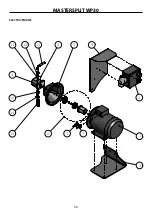
Страница 56: ...MASTERSPLIT WP30 56 1 2 3 4 5 6 7 7 8 9 10 11 12 13 14 15 ELECTRIC ENGINE ...

Страница 57: ... 4 55306330 Hydraulic pump 1 5 10907 Flange for pump 1 6 10908 Coupling 1 7 90127 Pullremover M32 x 1 5 2 8 10690 Key pump motor 1 9 30901 Support for electornicbox 1 10 90038 Spindle 1 25 mm 1 11 30668 Hydraulic hose 1 2 850 mm SM TR 1 30621 Hydraulic hose 1 2 800 mm SM 1 12 90086 Doublenipple 3 4 1 2 1 13 10621 Seal USIT 3 4 1 14 90126 Tightener 1 15 30631 Suction hose 1 270 mm SM TR 1 30672 Suc...

Страница 58: ...MASTERSPLIT WP30 58 1 2 3 4 5 6 7 8 9 10 11 12 13 COMBUSTION ENGINE ...

Страница 59: ...04 Hydraulic pump 1 3 11005 Flange for pump 1 4 10690 Key SNP2 pump motor 1 5 55307140 Coupling Vanquard 1 31004 Coupling Honda 1 6 31001 Bed for compustion engine 1 7 90172 Spark plug Vanquard 1 90175 Spark plug Honda 1 8 30666 Hydraulic hose 1 2 800 mm PM 1 30667 Hydraulic hose 1 2 800 mm PM TR 1 9 90083 Doublenipple 1 2 1 2 1 10 10620 Seal USIT 3 4 1 11 2711 Spindle 3 4 25 mm 1 12 90126 Tighten...

Страница 60: ...MASTERSPLIT WP30 60 17 1 1 2 3 4 5 6 7 7 8 9 9 11 12 13 13 14 15 16 16 10 TRANSPORTATION BASE FOR PUBLIC ROADS EXTRA EQUIPMENT ...

Страница 61: ...0809 Light set 1 8 30812 Fastening for fender right 1 9 10804 Fenders 2 10 30811 Fastening for fender left 1 11 30103 Lockning 1 12 30810 Sleeve for Coupling 1 13 30804 Front and back bracket for pullbeam 2 14 30805 Front bracket for pullbeam 1 15 30806 Back bracket for pullbeam 1 16 30813 Fastening for pullbeam 2 17 30808 Underrun protection 1 TRANSPORTATION BASE FOR PUBLIC ROADS EXTRA EQUIPMENT ...

Страница 62: ...pling 1 3 30801 Extension for pullbeam Mobil 1 4 10811 Cam plate bracket 1 5 10809 Cam plate 1 6 30807 Axle without brakes 1 7 10807 Light set 1 8 30812 Fastening for fender right 1 9 10804 Fenders 2 10 30811 Fastening for fender left 1 11 30103 Lockning 1 TRANSPORTATION BASE EXTRA EQUIPMENT NOTE NOT FOR PUBLIC ROADS ...

Страница 63: ...xtra equipment 2 3 30503 Lifters midbeam Extra equipment 1 4 55307060 Hook Extra equipment 1 5 30505 Lock 1 6 30507 Feed table support 1 7 55306640 Roll 1 8 30303 Frame of support roller 1 9 55307260 Flange bearing 2 10 30304 Supportroller 1 11 90035 Pin 5 mm 2 12 90039 Washer 50x62x3 0 6 SHAFT AND LOADERS EXTRA EQUIPMENT ...

Страница 64: ...MASTERSPLIT WP30 64 1 Part Order No Item Note Pcs 1 55306415 Crossblade 6 section extra equipment 1 CROSSBLADE 6 SECTION EXTRA EQUIPMENT ...

Страница 65: ...ut the manufacturer s permission insufficient maintenance non original parts The warranty does not cover wearing parts Send faulty parts carriage paid to the manufacturer for inspection Repairs will be con ducted by Farmi Forest Oy or an authorized expert The warranty is valid only if the bottom part of this page is filled in and returned to the manufacturer within 14 days of receipt of the produc...

Страница 66: ...dress Dealer s tel Product and type Serial number PRODUCT REGISTRATION FORM Return to the manufacturer Date of delivery _____ _____ 20_____ Dealer Dealer s address Dealer s tel Customer Customer s address Customer s tel E mail Product and type Serial number ...

Страница 67: ......

Страница 68: ...Farmi Forest Corporation Ahmolantie 6 FIN 74510 Iisalmi Finland Puh 358 0 17 83 241 Fax 358 0 17 8324 372 www farmiforest fi ...

Отзывы: