background image

12

Assembly - 1066 & 1076 Conventional Auger

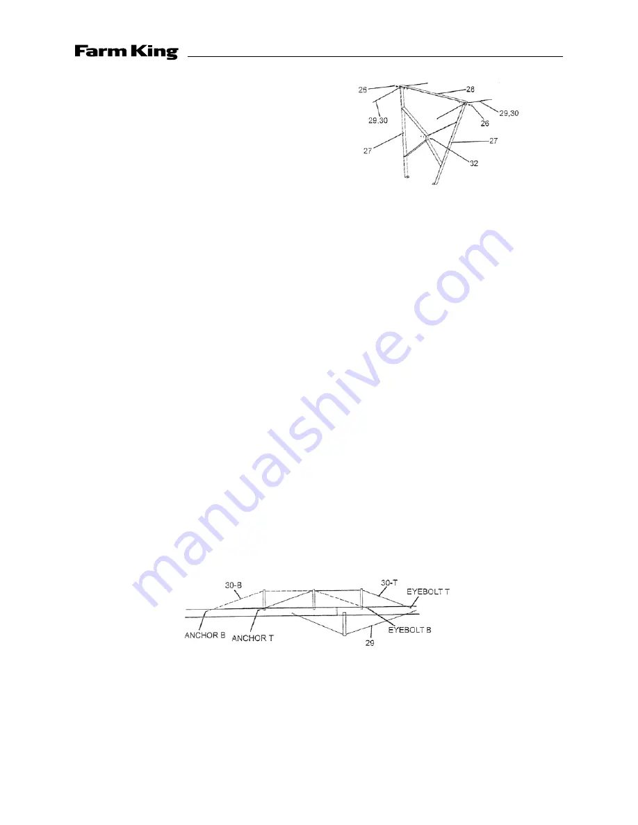
8.  Assemble the truss risers as shown to 

the right, using two supports (Ref. #27), 
one 3/8" x 1" bolt, nut and lockwasher 
combination (Ref. #32), one cross brace 
(Ref. #28) and two 3/8" x 1-1/4" bolt, nut 
and lockwasher combinations (Ref. #26) 
per riser.

9.  Mount the truss riser assemblies as instructed below 

 
1066 Model
 
Mount the first truss riser assembly on the flange ring using the 3/8" x 1" bolt, nut and 
lockwasher combinations (Ref. #32). Mount the second and third truss riser assemblies on the 
truss mounts located on the top tube using 3/8" x 1" bolt, nut and lockwasher combinations 
(Ref. #32). Install the 3/16" dia. truss cables (Ref. #30) using two cable clamps (Ref. #31) and 
one cable thimble (Ref. #31) on each upper cable end. Be sure to run the cable through the 
truss riser assemblies as shown. Tighten the cables with the eyebolts on the lower cable ends 
to keep the auger straight. 
 
Mount the undertruss riser assembly on the truss mount located on the lower tube using 3/8" 
x 1" bolt, nut and lockwasher combinations (Ref. #32). Install the 1/4" dia. truss cables (Ref. #29) 
using two cable clamps (Ref. #31) and one cable thimble (Ref. #31) on each upper cable end. 
Be sure to run the cable through the truss riser assembly as shown. Tighten the cables with 
the eyebolts on the lower cable ends to keep the auger straight. NOTE: Do not over-tighten the 
undertruss. Over tightening the undertruss will cause the auger to bow down when the auger 
is raised. 
 
1076 Model
 
Mount the three truss riser assemblies on the truss mounts located on the top tube using 
3/8" x 1" bolt, nut and lockwasher combinations (Ref. #32). Install the top pair (T) of 1/4" dia. 
truss cables (Ref. #30) using two cable clamps (Ref. #31) and one cable thimble (Ref. #31) on 
the upper cable ends. Install the bottom pair (B) of 1/4" dia. truss cables (Ref. #30) using two 
cable clamps (Ref. #31) and one cable thimble (Ref. #31) on the upper cable ends. Both pairs 
of cables go over the center riser. Be sure to run the cable through the truss riser assembly as 
shown. Tighten the cables with the eyebolts on the lower cable ends. Adjust both top truss "T" 
and bottom truss "B" to hold the auger straight. This process is trial and error, and experience 
with trusses is helpful. 
 

Mount the undertruss riser assembly on the truss mount located on the lower tube using 3/8" 
x 1" bolt, nut and lockwasher combinations (Ref. #32). Install the 1/4" dia. truss cables (Ref. #29) 
using two cable clamps (Ref. #31) and one cable thimble (Ref. #31) on the upper cable ends. 
Be sure to run the cable through the truss riser assembly as shown. Tighten the cables with 
the eyebolts on the lower cable ends to keep the auger straight. NOTE: Do not over-tighten the 
undertruss. Over tightening the undertruss will cause the auger to bow down when the auger 
is raised.

Содержание 1066

Страница 1: ...Operator and Parts Manual 112010 Conventional Auger Model 1066 1076 SZ000252...

Страница 2: ......

Страница 3: ...ons 11 Assembly Instructions PTO Drive 15 Parts 16 1066 and 1076 Parts 16 Decals 21 PTO Drive 22 6005 Gear Box 23 Warranty 24 Manufacturer s statement for technical reasons Buhler Trading Inc reserves...

Страница 4: ...has read the operator s manual and thoroughly understands safe and correct operating procedures Make sure unauthorized people do not operate or are not in the vicinity of the auger while it is in ope...

Страница 5: ...ly in the following conditions While unit is in operation When moving the auger When raising or lowering the auger Maximum elevation is determined by interference between track car and auger structure...

Страница 6: ...trical malfunction can cause electrocution of the operator or bystanders Observe the following rules Disconnect power and electrical driven units before resetting motor overloads Do not operate electr...

Страница 7: ...jury or death Shear bolt failure indicates an overload on the auger To remedy the problem 1 Reduce flow into the intake of the auger Wet grain requires more power to operate the auger The flow must be...

Страница 8: ...8 Assembly 1066 1076 Conventional Auger 1066Trussing 1076Trussing...

Страница 9: ...066 1076 Conventional Auger Keep all shields in place during operation NOTE Use a 3 8 x 1 1 4 Grade 2 shear bolt Using other than a Grade 2 bolt may result in damage to the drive components 1066 Model...

Страница 10: ...10 Assembly 1066 1076 Conventional Auger Keep all shields in place during operation 4 and 6 Bolt Hub Assembly Head Drive Assembly...

Страница 11: ...2 bolt nut and lockwasher combinations Ref 25 NOTE Do not fully tighten the bolts in the flange ring connection the first time Work around the flange at least twice to gradually pull the connection t...

Страница 12: ...wer cable ends to keep the auger straight NOTE Do not over tighten the undertruss Over tightening the undertruss will cause the auger to bow down when the auger is raised 1076 Model Mount the three tr...

Страница 13: ...n Ref 118 from the end of the track install track car Ref 50 onto the top end of the track and then replace track stop pin prior to using the auger Failure to do so could cause the auger to collapse A...

Страница 14: ...aded between the mounting plate and the cross shaft as shown danger Winch must be aligned with cable so that the cable does not stack on one side of the drum Do not allow the cable to become slack on...

Страница 15: ...sing 1 2 x 3 4 bolt and lockwasher Ref 77 3 Install the Implement Input Driveline hanger Ref 85 to the mount on the side of the auger tube using a 3 8 x 1 bolt nut and lockwasher combination Gearbox i...

Страница 16: ...7240 Top Driveline Section w Couplers 240 Long Under Shield 1 1 7 SZ5128241 Lower Driveline Section 240 Long Under Shield 1 1 8 SZ5127148 Top Driveline Section 147 1 2 Long Under Shield 1 SZ5127235 To...

Страница 17: ...pindle 114 Track 1 35R SZ0318254 Undercarriage Lift Arm 254 Right 1 SZ0318252 Undercarriage Lift Arm 252 Right 1 35L SZ0319254 Undercarriage Lift Arm 254 Left 1 SZ0319252 Undercarriage Lift Arm 252 Le...

Страница 18: ...le Clamp 2 2 56 SZ0212505 1 4 Aircraft Cable 105 1 SZ0212518 1 4 Aircraft Cable 112 1 58 SZ126098 BLT HHCS 1 2 13 UNC 3 1 2 G8 2 SZ127012 1 2 Lock Washer 2 SZ125010 1 2 Hex Nut 13 UNC G5 2 59 SZ021111...

Страница 19: ...O 1 1 81 SZ0161348B Non Separable Shielded IID w Shear Clutch 1 1 SZ126067 BLT HHCS 3 8 16UNC 1 1 2 1 1 SZ125030 Nut LCK 3 8 16UNC Nylock 1 1 82 SZ6007025 7 16 x 2 1 2 Spiral Expand Pin 1 1 83 SZ41930...

Страница 20: ...0 1 2 x 1 1 4 Wheel Bolt 8 12 135 SZDC 1200 Dust Cap 8 SZDC13 Dust Cap 2 136 SZLM11949 Outer Bearing Cone 2 SZ100125 Outer Bearing Cone 2 137 SZLM11910 Outer Bearing Cup 2 SZ100126 Outer Bearing Cup 2...

Страница 21: ...A 1 SZ06057 Grease Gun Silhouette 1 SZ06059 WARNING Contact with moving parts may result in a serious injury or death 1 SZ06075 DANGER Shield missing 5 SZ06078 NOTICE Avoid over feeding 1 SZ06081 STOP...

Страница 22: ...Repair Kit 1 3 SZ6003806 3 8 x 1 1 4 Grade 2 Shear Bolt w Locknut 1 4 SZ101633 14N Cross Bearing Kit Complete 2 5 SZ188 13481 1 x 1 1 8 Rectangular Shaft w 14NYoke 22 3 4 Long 1 6 SZ128 1200 14N Shiel...

Страница 23: ...t 1 7 SZPG 1511 Shim 005 SZPG 1512 Shim 0075 SZPG 1513 Shim 010 8 SZPG 1600 Snap Ring 1 9 SZPG 1651 Key 2 10 SZ8742128904 Grease Seal Input Shaft 1 11 SZPG 1471 Grease Seal Output Shaft 1 12 SZ100126...

Страница 24: ...eplacement as part of normal maintenance Also Buckets and Bucket Tines carry no warranty Bent Spears carry no warranty Snowblower Fan Shafts carry no warranty Mower Blades carry no warranty Portable A...

Страница 25: ...rranty Claim Forms with all requested information properly completed Warranty Claims must be submitted within a thirty 30 day period from date of failure repair Warranty Labor Any labor subject to war...

Страница 26: ...s subject to any existing conditions of supply which may directly affect Buhler Industries Inc s ability to obtain materials or manufacture replacement parts Buhler Industries Inc reserves the right t...

Страница 27: ......

Страница 28: ...tries Inc 1330 43rd Street NW Fargo ND USA 58102 Ph 701 282 7014 Fax 701 282 5865 Toll Free 888 524 1004 E mail info buhler com www farm king com Equipment shown is subject to change without notice 20...

Отзывы: