www.fanox.com
EN_FANOXTD_GUIDE_SIL_OCEFPrimaryDist_SILA_R002.doc 10 / 36
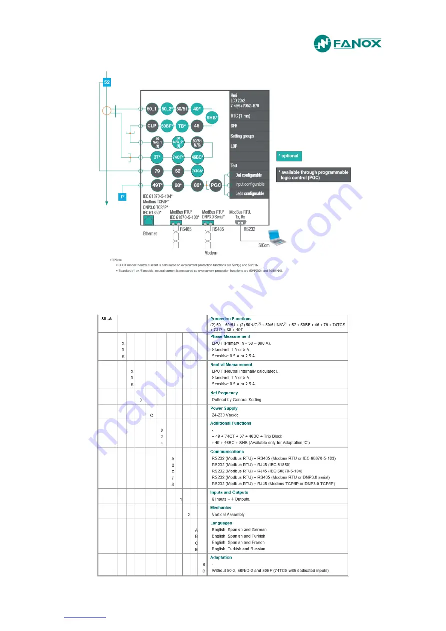
3. FUNCTIONAL DIAGRAM
4. SELECTION & ORDERING CODES
Страница 1: ...www fanox com EN_FANOXTD_GUIDE_SIL_OCEFPrimaryDist_SILA_R002 doc 1 36 INSTALLATION COMMISSIONING GUIDE SIL A Overcurrent Earth Fault Protection Relay...
Страница 2: ...INTERFACE 8 2 1 Relay front part 8 2 2 LED indicators 8 2 3 How to install SICOM software 9 2 4 Setting up the session Password and access levels 9 3 FUNCTIONAL DIAGRAM 10 4 SELECTION ORDERING CODES...
Страница 3: ...ing protocol is a certificate that relay has passed all factory testing process with correct results In case some fault is detected consider putting into quarantine period the relay and contact Fanox...
Страница 4: ...in date and time Besides the possibility of using external battery power together with the possibility of activating the trip contact from the test menu allows the trip circuit to be tested before the...
Страница 5: ...and dwon buttons to increase or decrease the contrast 1 3 2 Test menu NOTE When performing test menu protection won t be available and it will be possible to open circuit breaker Only authorized perso...
Страница 6: ...52 activated OK Led 79 Led 79 activated OK Output 1 Output 1 activated OK Output 2 Output 2 activated OK Output 3 Output 3 activated OK Output 4 Output 4 activated C Skip from test menu 1 4 Relay inst...
Страница 7: ...gital 2 common output D4 Digital input 2 D17 D18 NO digital output 3 D5 Common inputs 1 and 2 D19 D20 NO digital output 4 D6 Digital input 3 D21 Auxiliary voltage D7 Digital input 4 D22 Auxiliary volt...
Страница 8: ...36 1 6 Connection diagram 2 USER INTERFACE 2 1 Relay front part 2 2 LED indicators The SILA front panel has 8 LEDs The operation of the LED indicators can be checked from the test menu The user can c...
Страница 9: ...ommunications and to change the equipment settings or configuration using the HMI Depending on the access level it may or may not be possible to perform the operations shown on the table below ACCESS...
Страница 10: ...www fanox com EN_FANOXTD_GUIDE_SIL_OCEFPrimaryDist_SILA_R002 doc 10 36 3 FUNCTIONAL DIAGRAM 4 SELECTION ORDERING CODES...
Страница 11: ...curve IEC very inverse curve IEC extremely inverse curve IEC long time inverse IEEE Inverse curve IEEE very inverse curve IEEE extremely inverse curve Defined Time Time Delay 0 00 to 300 s step 0 01 s...
Страница 12: ...ation level 95 Instantaneous deactivation Timing accuracy for IEC and IEEE curves selection 30 ms or 5 greater of both Timing accuracy for defined time curve selection If Time Delay 0 00 to 0 02 s 50...
Страница 13: ...o the programmable logic 74CT Function Enable Yes No Time Delay 0 02 to 300 s step 0 01 s Timing accuracy 30 ms or 0 5 greater of both 37 Function Enable Yes No Current Tap 0 10 to 30 xIn step 0 01 Ti...
Страница 14: ...cteristics Number of records 168 Recording mode circular Sampling rate interval configurable through communications 1 60 min Record format Date Time IMAX in interval IMAX actual IA IB IC IN Inputs Sam...
Страница 15: ...dth 177 x 107 mm Depth 122 1 mm Weight 1 5 Kg IP 54 on pannel Depending on model 1 LPCT model 50N G 50 51N calculated neutral Standard model 50N G 50 51N G measured neutral 5 1 IEC60255 151 Curves The...
Страница 16: ...mathematical equation that defines the time in seconds as a function of the current B V A TD t P 1 adjusted I I V Which relate to the parameters figuring in the following table Parameters A P B Ext I...
Страница 17: ...specific meaning and is intended to be used by the functions of the device SIL A Adaptation B SIL A Adaptation C LEDs LED 1 LEDs LED 1 LED 2 LED 2 LED 3 LED 3 LED 4 LED 4 LED 5 LED 5 LED 6 LED 6 LED 5...
Страница 18: ...Trip 51G Trip LED 4 OR4_LACTH 50BF Trip SHB LED 5 OR4_LACTH 46 Trip 46 Trip LED 6 OR4_LACTH 74TCS Alarm 74TCS Alarm LED 52 OR4 52 Closed 52 Closed LED 79 OR4 79 Standby 79 Standby PHYSICAL OUTPUTS Ou...
Страница 19: ...51 block Not configured 50 51N G block Not configured Reset OR4_PULSE Local reset Remote Modbus reset Remote protocol reset Local reset Remote Modbus reset Remote DNP3 0 reset Settings group 1 Not con...
Страница 20: ...through the different menu items Each item can be activated or deactivated by pressing OK on it if the item is deactivated it is activated by pressing OK if the item is activated it is deactivated by...
Страница 21: ...ion screen Use the and keys to position the cursor over the digit that you want to change and assign a value to this digit using the and keys Once the date time has been entered press OK to change the...
Страница 22: ...st menu MEASUREMENTS and press key to overview the rest of the menus in the relay To return to standby screen press C key It is also possible to access to Fault reports by pressing key From the standb...
Страница 23: ...tting name is its value Depending on model States menu indicates the stuses of the relay activated or deactivated at real time From the standby mode screen press the OK key to access the first line of...
Страница 24: ...just the wanted value 51 protection function The parameters to adjust are Function Enable The function is available to work if this setting is YES or SHB While this permission is NO the function will...
Страница 25: ...SICom program The value of the CT Phase ratio and CT Neutral ratio general settings is the result given by dividing the number of turns on the primary winding by the number on the secondary winding F...
Страница 26: ...Use key to overview the options and press OK when Local COM Address option appears After inserting the password 5555 it will be possible to select the desired value Pressing OK key from the standby sc...
Страница 27: ...aused by activation or reset Associated measurement To delete the events from the relay it is necessary to insert the password 5555 from the events menu After the erasing of the events it will be appe...
Страница 28: ...interval configurable through communications 1 60 min Record format Date Time IMAX in interval IMAX actual IA IB IC IN To delete the demand from the relay it is necessary to insert the password 5555...
Страница 29: ...ress OK and use the and keys to position the cursor over the faults Once it is accessed to a fault report press OK to visualize the cause which has originated the fault report Pressing OK again it is...
Страница 30: ...ards 4 times rated current continuously 20 times rated current for 10s 80 times rated current for 1s In the following table the different injection modes are described CURRENT GENERATION INJECTION MOD...
Страница 31: ...t relay output contact is connected to generator tripping input in order to stop the generator hence the current injection after reaching adjusted tripping time This way relay will only withstand rate...
Страница 32: ...he current to achieve the function pick up and the function trip 8 3 1 Protection functions testing 50 instantaneous phase overcurrent protection Settings Function Enable YES Current Tap 1xIn Time 2 s...
Страница 33: ...ut 4 is activated LED 2 is activated TEST 2 Settings Function Enable YES Curve IEC Inverse Dial TMS 1 Current Tap 0 5xIn Theoretical tripping time 4 98 seconds fault current 2 A The following informat...
Страница 34: ...conds fault current 1A The following information will be checked Pick up at 110 of the tap Output 4 is activated LED 3 is activated TEST 3 Settings Function Enable YES Curve IEC Inverse Dial TMS 1 Cur...
Страница 35: ...tput 3 OK NOK Output 4 OK NOK Keypad OK NOK Auxiliary Power OK NOK Communications OK NOK Settings and configuration OK NOK Current measurements OK NOK Protection Functions 50 1 phase A OK 50 1 phase B...
Страница 36: ...www fanox com Installation_Guide_SIAB000B0021AA_Rev 02 36 36...