


ADVERTENCIA
Es fundamental que la caja de distribución eléctrica y los
tornillos estén bien asegurados a la estructura armada
y que sean capaces de soportar una carga de, al menos,
15,9 kg (35 lb). Si los tornillos no están correctamente
colocados, el ventilador podría caerse. (Figura 2)
ADVERTENCIA
Para evitar posibles descargas eléctricas, asegúrese
de que la electricidad esté desconectada en la caja de
fusibles principal antes de colgar el ventilador.
NOTA: Si no está seguro de si la caja de distribución
eléctrica tiene conexión a tierra, pida asesoramiento a
un electricista autorizado, ya que la conexión a tierra es
fundamental para un funcionamiento seguro.
ADVERTENCIA
Las aspas del ventilador deben estar suspendidas, al
menos, a 2 m (7´) del piso (Figura 1)
1.
Ajuste bien la caja de conexiones del techo apta para
soporte de ventilador en la estructura armada. Caja de
conexión no se suministra con el ventilador. (Figura 2)
Figura 1
Figura 2
Figura 3
Unidad de placa
para el techo
Figura 4
28
x 4
x 4
Arandela plana
Tornillo de madera
de cabeza plana de
ZŊ
Aditamentos utilizados:
2.
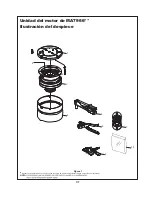
Extraiga los cuatro tornillos y las tuercas hexagonales
con arandela plana. Guárdelos para la reinstalación en
los pasos 7 y 8 de la página 30. (Figura 3)
NOTA: Se omiten los
cables de suministro
para mayor claridad.
Caja de distribución
eléctrica
Se recomienda que cada ventilador y el motor tiene el
UHVSDOGRGHPDGHUDFRQWUDFKDSDGDGHôÝDVHJXUDGRD
un elemento de la estructura de apoyo adecuada.
A 120 VAC de alimentación eléctrica, centrado en la
unidad de motor y por cable a una velocidad de 3 de
control (incluido) se requiere. La unidad de motor no
funcionará más de cuatro cabezal / montajes de lámina.
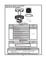
NOTA LA INSTALACIÓN
(QSULPHUOXJDUWDODGUHORVRULILFLRVJXtDVGHÝHQ
la base de contrachapado o viga de sujeción para evitar
que se raje o rompa. Instale la unidad de placa para el
techo en el techo con los tornillo de madera de cabeza
plana y las arandelas planas. (Figura 4)
Caja de electricidad
al mismo nivel del
techo acabado
&RQWUDFKDSDGRôÝGHJURVRUPtQ
Parte posterior asegurada a la viga
de la estructura.
14 pies máx. – motor al cabezal
4 pies mín.
(13½´ máx. – cabezal a cabezal)
EI Piso
EI Techo
No
menos de
2,13 m
Cómo instalación y cableado del ventilador de techo


