background image

1. 

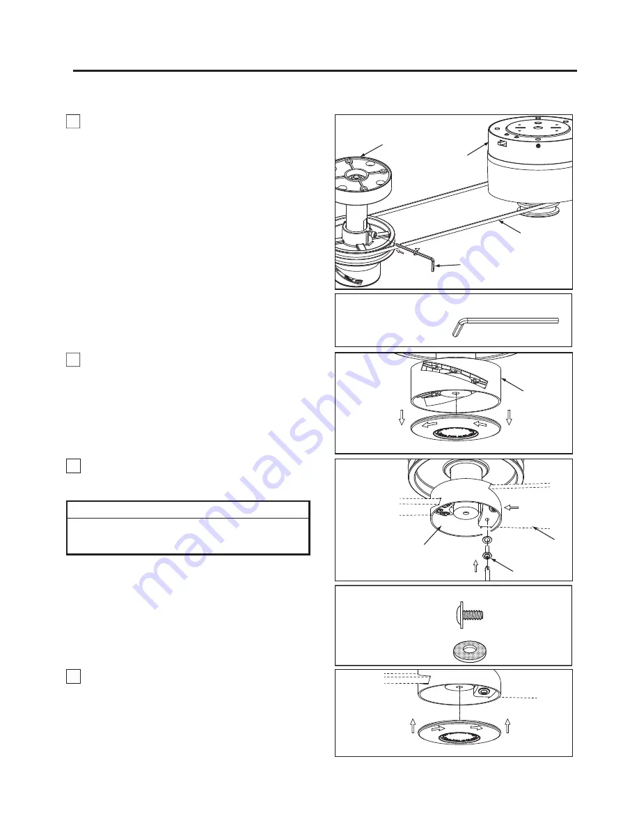
To adjust the vertical alignment of the belt, loosen the 

screw in the pulley assembly pulley with the supplied by 
allen wrench to adjust the pulley so that belt is parallel 
with the floor, then securely tighten the screw. (Figure 1)   


2. 

 Remove the end cap from the pulley assembly.

Retain the end cap for later. (Figure 2)


Figure 1

Pulley 
Assembly

Pulley
Assembly

Blade

ALLEN
WRENCH
6 x 90 x 32 mm

HARDWARE  USED:

13

How to Mount the Fan Blades

Pulley

Motor
Assembly

Assembly

Allen Wrench

Belt

Figure 2

Figure 4

Figure 3

HARDWARE  USED:

3/16

Ý

-24 Screws 

(3 per assembly)

x  6

x  6

FIBER WASHER

3/16

Ŋ

-24 

WASHER HEAD

SCREWS

3. 

Securely fasten the two blades (not included) with

 washer-head screws with fiber washers. Do not  

over-tighten. (Figure 3)


4. 

Assemble the end cap to the 

pulley

 assembly

by twisting in a clockwise direction. 

(Figure 4)


CAUTION

Do not connect fan blades until the fan is completely 
installed.  Hanging fan with blades connected may result 
in damage to the fan blades.

NOTE: Optional Wood Blade Set B7966** is available for 
this assembly.  Not for Damp Location usage.

Содержание B7966

Страница 1: ...For Fan Head Assembly HA7966 Net Weight 2 4 kg 5 29 lbs B7966 Net Weight 0 60 kg 1 32 lbs MA7966 Net Weight 9 3 kg 20 48 lbs OWNER S MANUAL READ AND SAVE THESE INSTRUCTIONS The Kellan Belt Driven Cei...

Страница 2: ...D LIFETIME WARRANTY Extends to the original purchaser of a Fanimation Fan 1 LIMITED LIFETIME MOTOR WARRANTY If any part of your fan motor fails due to a defect in materials or workmanship during the l...

Страница 3: ...y law This warranty gives you special legal rights and you may also have other rights that vary from state to state 10 A certain amount of wobble is normal and should not be considered a problem or a...

Страница 4: ...stration Figure 1 page 17 Check to see that you have received the following parts Hand held Remote Motor Assembly Ceiling Plate Assembly Housing Assembly MA7966 Motor Assembly and Hardware Parts Ident...

Страница 5: ...t description refer to exploded view illustration Figure 2 page 19 NOTE Optional Wood Blade Set B7966 is available for this assembly Not for Damp Location usage Head Assembly Unpacking Instructions an...

Страница 6: ...gentle updraft which forces warm air near the ceiling down into the occupied space Remember to adjust your thermostat when using your ceiling fan additional energy and dollar savings could be realize...

Страница 7: ...in fuse box at this time and remove the existing light xture Turning off wall switch is not sufficent To avoid possible electrical shock be sure electricity is turned off at the main fuse box before w...

Страница 8: ...Figure 4 Figure 4 WARNING The outlet box must be securely anchored and capable of withstanding a load of at least 35 lbs Hanger bracket must seat rmly against outlet box If the outlet box is recessed...

Страница 9: ...Figure 7 After splicing and making the wire connections the wires should be spread apart and turned upward with the grounded conductor and the equipment grounding conductor on one side of the outlet...

Страница 10: ...lat washers and securely tighten all hex nuts Figure 8 8 Assemble the housing to ceiling plate assembly using the previously removed screws and securely tighten all screws Figure 9 Housing Figure 9 Ho...

Страница 11: ...0RXQW WKH SXOOH DVVHPEO RQ WKH FHLOLQJ ZLWK lag bolts and flat washers The lag bolt will pass through the flat washer and into the building structure Figure 3 Pulley Assembly Mounting Cover Allen Wren...

Страница 12: ...ould hold the belting together after releasing the belt Figure 1 2 Punch two holes approximately 1 8 inch in diameter through the overlapping belts spacing them one inch apart with the punch tool supp...

Страница 13: ...n Blades Pulley Motor Assembly Assembly Allen Wrench Belt Figure 2 Figure 4 Figure 3 HARDWARE USED 3 16 24 Screws 3 per assembly x 6 x 6 FIBER WASHER 3 16 24 WASHER HEAD SCREWS 3 Securely fasten the t...

Страница 14: ...curity systems simply change the combination code in your transmitter and receiver To set the code perform these steps 7UDQVPLWWHU remove battery cover by pressing firmly below arrow and sliding batte...

Страница 15: ...the screw holes Including in the control Figure 1 1 Unthread two screws from the wall switch plate Figure 1 2 Install the control bracket with two 6 32x 1 screws And push the four plastic plug to cov...

Страница 16: ...state controls are not recommended choose an alternative control method CAUTION Make sure main power is turned off 4 Tighten set screw securely 5 Not considered a defect 3 FAN WOBBLES EXCESSIVELY 1 Fa...

Страница 17: ...illustration shown is not to scale or its actual configuration may vary Wires partially removed for clarity Insert FINISH CODES Refer to fan model number located on fan assembly Exploded View Motor A...

Страница 18: ...ail store for repair parts When ordering repair parts always give the following information 3DUW 1XPEHU 3DUW HVFULSWLRQ DQ 0RGHO 1XPEHU 2 0RWRU VVHPEO 0 1 HLOLQJ 3ODWH VVHPEO 3 RXVLQJ VVHPEO 3 Rivet T...

Страница 19: ...al Ref Description Part How To Order Parts Contact your retail store for repair parts When ordering repair parts always give the following information 3DUW 1XPEHU 3DUW HVFULSWLRQ DQ 0RGHO 1XPEHU 2 Bel...

Страница 20: ...10983 Bennett Parkway Zionsville IN 46077 Toll Free 888 567 2055 FAX 866 482 5215 Outside U S call 317 733 4113 Visit Our Website www fanimation com Copyright 2014 Fanimation 2014 09 V 01...

Страница 21: ...B7966 0 60 kg 1 32 lbs Apropiado para su uso con controles de velocidad de estado s lido ADVERTENCIA Soporte directamente desde la estructura del edificio para el unidad del cabezal Modelo N MA7966 U...

Страница 22: ...io descarga el ctrica y lesiones a personas Ventilador serie MA7966 Modelo Colgado del techo debe ser instalado con unidad del cabezal que se marcan en sus cartones se alar la adecuaci n a este modelo...

Страница 23: ...posible que tambi n goce de otros derechos que pueden variar seg n el estado 10 Es normal que se produzca un cierto movimiento oscilante y esto no debe considerarse un problema o defecto GARANT A LIM...

Страница 24: ...ectricista autorizado para instalar el ventilador L y q g m q x g m NOTA coloque las piezas de las bolsas de piezas individuales en un contenedor peque o para evitar que se extrav en Si faltan piezas...

Страница 25: ...LRV VLQ SUHYLR DYLVR 25 Figura 2 Unidad del cabezal Instrucciones de desembalaje e identificaci n de las piezas Bolsas de accesorios 1 Verifique que haya recibido las siguientes piezas Bolsas de acces...

Страница 26: ...salgunassugerencias para asegurar un rendimiento eficiente del producto Selecci n del lugar de montaje adecuado Los ventiladores de techo se deben instalar en el centro de la habitaci n a 2 13 m 7 pie...

Страница 27: ...GDG GH PRWRU QR IXQFLRQDUi PiV GH FXDWUR FDEH DO PRQWDMHV GH OiPLQD NOTA LA INSTALACI N 27 Requisitos el ctricos y estructurales cont Figura 3 Techo Vigas del techo Caja de distribuci n el ctrica Prof...

Страница 28: ...de madera de cabeza plana de Z Aditamentos utilizados 2 Extraiga los cuatro tornillos y las tuercas hexagonales con arandela plana Gu rdelos para la reinstalaci n en los pasos 7 y 8 de la p gina 30 F...

Страница 29: ...pelado o un cable verde con aislamiento Conecte los cables con cuidado usando un conector de cables Conecte con cuidado el cable del receptor blanco que viene del ventilador con el cable blanco neutr...

Страница 30: ...de techo utilizando las tuercas hexagonales y arandelas planas anteriormente extra das y f jelas adecuadamente Figura 8 8 Instale la carcasa a la Unidad de placa para el techo de techo utilizando los...

Страница 31: ...20 mm HARDWARE USED x 4 x 4 Arandelas planas Tirafondos Aditamentos utilizados Z 4 Instale la carcasa de montaje de la unidad del polea utilizando los tornillos anteriormente extra dos y f jelos todos...

Страница 32: ...emos de la correa y tire con fuerza Las pinzas deber an seguir sujetando la correa despu s de soltarla Figura 1 2 Perfore dos orificios de aprox 1 8 pulgadas de di metro a trav s de las correas montad...

Страница 33: ...2 Figura 4 Figura 3 Aditamentos utilizados Aditamentos utilizados 2 por conjunto x 6 x 6 Arandela de fibra Tornillos de cabeza FG 3 Asegure bien las aspas con tornillos de cabeza no incluido con torni...

Страница 34: ...pci n deslizando los interruptores de c digo hacia arriba o hacia abajo La configuraci n de f brica es en la posici n superior No utilice esta posici n Con un destornillador peque o o con una lapicera...

Страница 35: ...s tornillos Incluidos con el mando Figura 2 1 Retire los dos tornillos colocados en la plaza del interruptor de la pared Figura 1 2 Instale el soporte de control con los dos tornillos 6 32x 1 Empuje l...

Страница 36: ...del ventilador est n bien ajustados PRECAUCI N Aseg rese de que el suministro principal de electricidad est desconectado 3 Algunos motores de ventilador son sensibles a las se ales de los controles d...

Страница 37: ...7 1 2 3 8 Figura 1 Unidad del motor de MA7966 5 4 6 7 10 9 Ilustraci n del despiece Introduzcas los C DIGOS de acabo Consulte el n mero de modelo del ventilador ubicado en la unidad del ventilador NOT...

Страница 38: ...de cabeza plana 10 Tipo B Arandela plana 5 HDWMA7966 Unidad del motor de MA7966 HVWRUQLOODGRU 3KLOOLSV GH Lista de piezas Antes de desechar los materiales de embalaje aseg rese de haber extra do todas...

Страница 39: ...Arandela de 2 54 x 5 92 x 0 89 mm 8 C mo hacer un pedido de piezas Al hacer un pedido de piezas de repuesto proporcione siempr e la siguiente informaci n 1 PHUR GH SLH D HVFULSFLyQ GH OD pieza 1 PHUR...

Страница 40: ...14 Fanimation 2014 09 V 01 10983 Bennett Parkway Zionsville IN 46077 Llame sin cargo al 888 567 2055 FAX 866 482 5215 Desde fuera de los EE UU llame al 317 733 4113 Visite nuestro sitio Web en www fan...

Отзывы: