


Cómo configurar su mando a distancia TR33WH
NOTA: Usted debe presionar el "botón de " en menos de un
minuto de reestablecida la alimentación al ventilador. No es
necesario volver a programar el control remoto al reemplazar la
batería. Sírvase notar que el control remoto puede programar
varios receptores.El límite de 60 segundos elimina dicha
necesidad.
34
2.
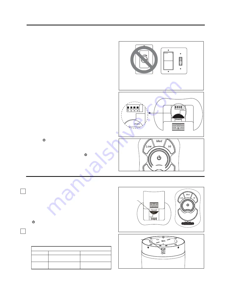
Si se desea que el flujo del aire vaya en la dirección
opuesta, apague el ventilador y espere a que se detengan
las palas. Deslice la carcasa de la cubiertapara visualizar
el interruptor del reverso. (Figura 2)
2.
3.
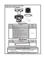
Después de instalar la unidad y de reestablecer la
alimentación al ventilador, mantenga presionado el
"botón de " entre 1 y 5 segundos, la luz parpadeará dos
veces, lo que indica que se ha completado el proceso de
aprendizaje. (Figura 3)
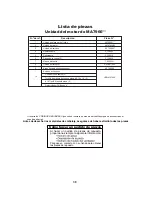
Configuración del código:
La unidad del control remoto
cuenta con 16 combinaciones de código diferentes. Para
evitar posibles interferencias desde o hacia otras unidades
de control remoto como la de apertura de puertas del garaje,
la alarma del auto o sistemas de seguridad, simplemente
cambie la combinación del código en su transmisor y receptor.
Para configurar el código, siga los siguientes pasos.
Transmisor:
retire la cubierta de la batería. Presione
firmemente la flecha que se encuentra debajo y deslice
para retirar la cubierta de la batería. Seleccione su opción
deslizando los interruptores de código hacia arriba o
hacia abajo. La configuración de fábrica es en la posición
superior. No utilice esta posición. Con un destornillador
pequeño o con una lapicera deslice firmemente hacia
arriba o hacia abajo (Figura 2). Vuelva a colocar la
cubierta de la batería en el transmisor.
1.
Funcionamiento y uso del transmisor remoto (Figura 1):
Instale la batería de 3 voltios (si no se va a utilizar por largos
períodos de tiempo, retire la batería para evitar daños al
transmisor). Guarde el transmisor lejos del exceso de calor
o humedad.
Botón HI (alto) – velocidad del ventilador alta
Botón MED (medio) – velocidad del ventilador media
Botón LOW (bajo) – velocidad del ventilador baja
Botón OFF (apagado) – ventilador apagado
Información sobre el interruptor de reversa
Temporada
Verano
Invierno
Dirección de rotación
En dirección de las
manecillasdel reloj
En dirección contraria
a las manecillas del reloj
Derecha
Izquierda
Posición del interruptor
Cómo instalar su de TR33WH mando a distancia
Figura 2
1 2 3 4
ON ECE
REVERSE
SWITCH
Detalle del transmisor
remoto
ON ECE
Batería
de 3V
BATERIA DE 3V,
CR2032
2PCS
Mando a
distancia
Figura 1
Solo para referencia visual-
no ha sido
diseñado para cubrir todos los tipos de
controles
Figura 1
ECE
Figura 2
Figura 3
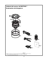
1.
IMPORTANTE:
El uso de un regulador de la intensidad completa
(no incluido) para controlar la velocidad del ventilador
dañará el dispositivo. Para reducir el riesgo de incendio
o descarga eléctrica, no utilice dicho regulador para
controlar la velocidad del ventilador. (Figura 1)


