


1.
Securely attach the ceiling junction box
acceptable for
fan support
into the building structure. Junction box
is not supplied with the fan. (Figure 2)
Figure 1
WARNING
To avoid possible electrical shock, be sure electricity is
turned off at the main fuse box before hanging.
NOTE: If you are not sure if the outlet box is grounded,
contact a licensed electrician for advice, as it must be
grounded for safe operation.
WARNING
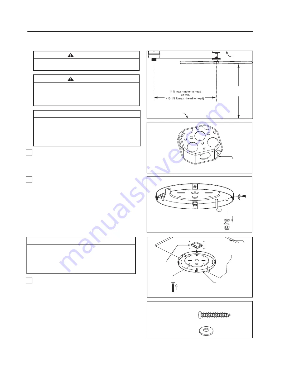
The fan must be hung with at least 7´ of clearance from
floor to blades. (Figure 1)
Floor
Ceiling
No
less than
7 ft
Figure 2
Figure 3
NOTE: Supply wires
omitted for clarity
Outlet Box
Ceiling Plate
Assembly
<RXZLOOILUVWGULOOÝSLORWKROHVLQWRWKHSO\ZRRG
base
or supporting member to prevent splitting or
cracking. Mount the ceiling plate assembly on the
ceiling with four pan head wood screws and flat
washers. (Figure 4)
Figure 4
ʆ
WARNING
The outlet box must be securely anchored and capable
of withstanding a load of at least 35 lbs. Hanger bracket
must seat
¿
rmly against outlet box. If the outlet box is
recessed, remove wallboard until bracket contacts box.
If bracket and/or outlet box are not securely attached,
the fan could wobble or fall.
ʆ
8
How to Hang and Wire Your Motor Assembly
x 4
x 4
FLAT WASHER
PAN HEAD
WOOD SCREWS
HARDWARE USED:
#6-18 x 1.5
Ŋ
2.
Remove the four screws and hex nuts with flat washer
from the ceiling plate assembly. Retain the screws, hex
nuts and flat washers for reinstallation in steps 7 and 8 of
page 10. (Figure 3)
INSTALLATION NOTE
It is recommended that each fan and the motor have
ôÝSO\ZRRGEDFNLQJVHFXUHGWRDVWUXFWXUDOPHPEHUIRU
adequate support . A 120 VAC electrical feed, centered
XQGHUWKHPRWRUXQLWDQGZLUHGWRDVSHHGFRQWURO
(supplied) is required.
7KHPRWRUXQLWZLOOQRWRSHUDWH
more than 4 head/blade assemblies.
Plywood (¾
Ý
thick min.)
Backing Secured to
Structural Member
Outlet Box Flush
to Finished
Ceiling


