4.
JSC —
Fasten the trough end to the seal housing using the flat
head hex socket cap screws included in the drive shaft kit. Refer
to Table 3 for torque value. Proceed to Step 6.
5.
JF —
(NOTE: If the driven shaft has not been machined to
Falk’s taper bore specifications per Falk Engineering
377-140 and a straight shaft is to be utilized, refer to Falk
Engineering 377-144 for instructions). If a backstop is
required and was Factory installed, remove the cover from
input end of hollow shaft bore and save. Install the thrust
plate and retaining ring in the hollow shaft (Refer to Figure
4). Installation of internal backstops NOT Factory installed,
may require removal of the mounting flange, Ref. #12, Page
14. Proceed to Step 6.
Installation
6.
JR, JF & JSC —
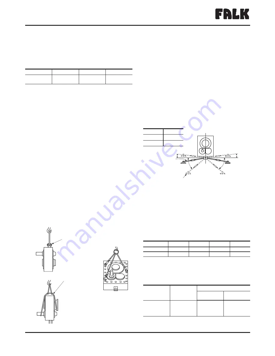
Refer to Figure 7 for recommended lifting
method. In order to sling JR & JF as illustrated, install the tie
rod fastener in the tie rod anchor brackets. Sling the drive
from the fastener as shown. For vertical installation, use (3)
eye bolts as illustrated. Eyebolt sizes are ½" (12,70 mm) for
4407/ thru 4507 and ¾” (19,05 mm) for 4608. DO NOT
remove sling until drive is secured to shaft. Before lifting the
drive into position, rotate the input shaft until the hollow
shaft keyway will be in position to line-up with the driven
shaft key. JF proceed to Step 11; JSC to Step 12.
7.
JR —
If the drive was received with a backstop installed, the
backstop must be temporarily removed to facilitate mounting
when the following conditions prevail:
Ratio J05 where rotation arrow indicates
Counter-Clockwise H.S. shaft rotation.
Ratio J09, J14, or J25 where rotation arrow indicates
Clockwise H.S. shaft rotation.
Refer to Section II, Figure 14 for Sizes 4407 thru 4507
and remove cover Ref. #19 and backstop Ref. #5A1. For
Size 4608, refer to Figure 15 and remove backstop Ref.
#5A. Proceed to Step 8.
8.
JR —
Lift the drive into position and slide onto the drive shaft
taking care that the driven shaft key seats into the hollow
shaft keyway. DO NOT hammer or use excessive force. Refer
to Figure 8 for installation of the tie rod. The exact position
of the tie rod may vary within the range shown. For tie rod
mountings other than shown, refer to Falk. If it is necessary
to shorten the tie rod, cut the excess from either threaded
end.
The support to which the clevis bracket is to be fastened
must sustain the torque reaction shown in Table 4. The
maximum load reaction through the tie rod occurs when the
tie rod is located in the extreme (40°) off angle position. The
magnitude of this force is reduced approximately 30% when
the tie rod is mounted in the preferred position shown in
Figure 8. Use Grade 5 fasteners to anchor the clevis
bracket; see Table 5 for the fastener diameter and tightening
torque.
The Falk Corporation, P.O. Box 492, Zip 53201-0492
378-102
3001 W. Canal St., Zip 53208-4200, Milwaukee, WI USA Telephone: 414-342-3131
August 2004
Fax: 414-937-4359 e-mail: [email protected] web: www.falkcorp.com
Supersedes 6-92
®
a good name in industry
Owners Manual
•
Quadrive Shaft Mounted Drives
(Page 6 of 56)
Sizes 4407/M4407-4608/M4608
SLING AROUND
SEAL HOUSING
AND INPUT SHAFT
SLING FROM
LONG FASTENER
WITH NUT
Figure 7
TABLE 3 — (Size 4407 JSC) Trough End Fastener
Size (UNC) & Tightening Torques
lb-in (Nm) Non Lubricated
Fasteners
2.000
2.437
3.000
3.437
.625-11UNC
.625-11UNC
.750-10UNC
.750-10UNC
2190 (247)
2190 (247)
3960 (447)
3960 (447)
TIE ROD
AND
TURNBUCKLE
CLEVIS
BRACKET
A
A
2°
2°
Figure 8 — Tie Rod Mounting Positions
6 O’Clock Mounting Position Shown
Drive Size
A
4407
2 °
4608
5 °
TABLE 4 — Load Reaction Through Tie Rod
Drive Size
4407
4415
4507
4608
Load lbs
H
17900
21600
28600
33500
Load (N)
H
(79600)
96100
127200
149100
H
Load includes moment due to motor and motor mount with tie rod at
maximum angle.
TABLE 5 — Tie Rod Clevis Bracket Fastener
Tightening Torque
Drive
Size
Fastener
Size
†
Tightening Torque – lb-in (Nm)
Steel
Foundation
Concrete
Foundation
4407
1.000-8UNC
6800 (768)
5600 (633)
4415
1.250-7UNC
12600 (1 424)
10400 (1 175)
4507
1.250-7UNC
12600 (1 424)
10400 (1 175)
4608
1.250-7UNC
12600 (1 424)
10400 (1 175)
†
Grade 5 fasteners required.


