12
Operating the Controller:
a) Start a timing cycle: Press any product key (1 to 4)
to start a timing cycle. If key is programmed,
the correct time will be displayed and will immediately
start to count down and LED above key will flash.
DONE will display when cook cycle has ended and
alarm will sound. If DONE is displayed immediately
and alarm sounds, the key has not been programmed
See Section 6.3 for programming details.
b) Stop a timing cycle: Press and hold an active
product key for 3 seconds, or press key 3 times within
2 seconds.
c) Respond to a DONE alarm: Cancel signal by pressing
same product key used to start timing cycle.
d) Multiple timing cycles: If a second or third product
key is pressed while the first is still active, the shortest
time remaining key is displayed and only the LED
above key flashes, the other(s) remain constantly lit.
Once shortest time programme ends and is
accepted, next shortest is displayed and LED above
flashes. Note: All product key timers will count down
although not displayed until shorter one ends.
e) Action Alarms (Shake, etc.): If control is programmed
for action alarm, they will signal at a preset time
during the timing cycle. The signal, a dual-rhythm
beeping, will last 5 seconds and then self-cancel.
The display will flash action alarm time and then will
continue counting towards 0:00.
f) Viewing Actual/Set Temperatures: Pressing the
temperature key once will display “AXXX” where XXX
is actual temperature in degrees (C or F depending on
how controller is programmed – See Section 6.3).
Pressing the temperature key again within 5 seconds
will display “PXXX” where XXX is the programmed
Set temperature of the controller in degrees (C or F
depending on how controller is programmed – See
Section 6.3). If temperature key is not pressed again
within 5 seconds, display returns to idle or timer mode.
6.3 PROGRAMMING THE G402F
Display Descriptions
Louu
Controller is in operating mode. Actual vat temperature is
more than 10° below programmed vat temperature.
rEdy
Controller is in operating mode. Actual vat temperature is
within proper cooking temperature range. Vat is ready to
begin a cook cycle.
HI
Controller is in operating mode. Actual vat temperature is
more than 30° above highest programmed vat
temperature.
Prob
Control probe is either open circuited or short circuited.
Display will be accompanied by an audible alarm if
shorted. Check or replace probe.
2:30
The control is in operating mode and a cook cycle is in
progress.
done
The control is in operating mode and a cook cycle has
been completed. Display will be accompanied by a
pulsing audible alarm.
6.3.1 Programming temperature set point and
temperature scale. (Factory set for 180
⁰⁰⁰⁰
C,
range available is 30
⁰⁰⁰⁰
C to 190
⁰⁰⁰⁰
C)
a) Press and hold temperature key for 3 seconds.
“Prog” will be displayed. Then press DOWN (key 1)
or UP (key 4) key.
b) The display will show either “
⁰
C” or “
⁰
F” (degrees
celsius or degrees fahrenheit). Once desired
temperature scale is displayed, press temperature key
to accept/enter.
c) Display will now alternate between “Sett” and
“XXXZ” (where X denotes temperature and
Z indicates temperature scale).
d) Adjust temperature using DOWN (key 1) and UP (key
4) keys. The longer key is pressed, the faster
temperature scrolls.
e) When desired temperature has been reached, press
temperature key to accept/enter.
f) To exit temperature programming, press temperature
key again.
6.3.2 Programming a Product Cycle Time
and Action Alarm
a) Press and hold P key for 3 seconds. “Prog” will
display.
Note:
Programming
mode
will
exit
automatically if no keys are pressed within 2 minutes.
b) Select a product key to program (1 to 4). The display
will alternate between “ti-z” and “X:XX” where z is
the number of the key pressed and X:XX is the set
time in minutes and seconds.
c) Adjust the time up or down using the DOWN (key 1)
and the UP (key 4) keys. The longer key is held,
the faster time will scroll.
Содержание G402F
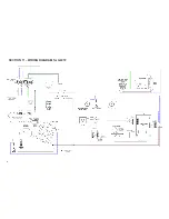
Страница 16: ...SECTION 11 WIRING DIAGRAM for G401 16...
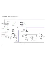
Страница 17: ...SECTION 11 WIRING DIAGRAM for G401F 17...
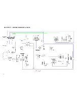
Страница 18: ...SECTION 11 WIRING DIAGRAM for G402 18...
Страница 19: ...SECTION 11 WIRING DIAGRAM for G402F 19...
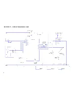
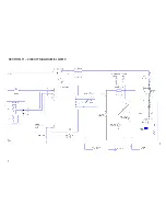
Страница 20: ...SECTION 11 CIRCUIT DIAGRAM for G401 20...
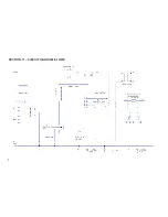
Страница 21: ...SECTION 11 CIRCUIT DIAGRAM for G401F 21...
Страница 22: ...SECTION 11 CIRCUIT DIAGRAM for G402 22...
Страница 23: ...SECTION 11 CIRCUIT DIAGRAM for G402F 23...

