background image

V0612 - 20i-T / 30i-T - Installation/Operation - Appendix - (27/32)

4  Appendix

4.1 UL seal

See "UL seal" page 16.

4.2 CE seal

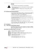
Warning

Before starting up the DRO, carefully read the instructions of Chapter 2 in 
the Installation Manual.

The DRO must not be powered-on until verifying that the machine complies 
with the "89/392/CEE" Directive.

4.2.1 Declaration of conformity

Manufacturer:    

Fagor Automation, S. Coop

.

Barrio de San Andrés 19, C.P. 20500, Mondragón -Guipúzcoa (ESPAÑA)

We hereby declare, under our responsibility that the product:

Fagor Digital Readout:


20i-T, 30i-T

meets the following directives:

SAFETY: 

EN 60204-1Machine safety. Electrical equipment of the machines

ELECTROMAGNETIC COMPATIBILITY:

EN 61000-6-4 Emission
EN 55011

Radiated. Class A, Group 1.

EN 55011

Conducted. Class A, Group 1.

EN 61000-3-2 Harmonics
EN 61000-3-3 Flickers.
EN 61000-6-2 Immunity
EN 61000-4-2 Electrostatic discharges.
EN 61000-4-3 Radiofrequency Radiated Electromagnetic Fields.
EN 61000-4-4 Bursts and fast transients.
EN 61000-4-5 Shockwaves
EN 61000-4-6 Conducted disturbance induced by radio frequency fields.
EN 61000-4-8 Magnetic fields at mains frequency
EN 61000-4-11 Voltage fluctuations and Outages.
ENV 50204  

Electromagnetic fields radiated by wireless telephones.

As instructed by the European Community Directives on Low Voltage:
73/23/EEC, (and the 93/68/EEC amendment) on Machine Safety 89/392/EEC
and 89/336/EEC on Electromagnetic Compatibility.

In Mondragón, April 1st, 2005

All manuals and user guides at all-guides.com

Содержание 20i-T

Страница 1: ...utomation S Coop 20i T 30i T 20i T B 30i T B Installation Operation Manual Manual code 14460054 Manual version 0612 Software version 4 xx All manuals and user guides at all guides com a l l g u i d e...

Страница 2: ...Taper cone calculation 12 2 5 5 Calculator 13 2 5 5 1 Operating with the calculator 13 2 5 5 2 Recall and Reset modes 14 3 DRO installation 15 3 1 Installation of the built in model 15 3 2 Rear panel...

Страница 3: ...0 to 19 The 20i T model shows the active reference on the display at all times whereas the 30i T model only shows it when it is selected after pressing the reference key To select the axis or preset i...

Страница 4: ...code See the error table and PAR11 for more options Turns the DRO on or off Precautions Before disconnecting this unit from mains press this key so it saves the current position If the unit is turned...

Страница 5: ...lation parameter PAR04 radius diameter of the axis has been preset as 1 commutated Z axis as a single axis or combination of both Z1 and Z2 Only at the 30i T To display the Z axis position one or two...

Страница 6: ...nce to access the Home mode only to search home ABS In Absolute ABS when the ABS led is on it displays the distance from the present position of the axis to part zero D I In Incremental when the ABS a...

Страница 7: ...mental mode Press this key until the ABS LED is turned off Move the axis up to the face of the part to set it as part zero At this point one can proceed in two ways Preset the axis with a zero value b...

Страница 8: ...concluded Note By pressing this key until the ABS LED lights up the DRO will show the real position of the axis with respect to part zero 0 In absolute mode Press this key until the ABS LED is turned...

Страница 9: ...chine zero point home Fagor also offers encoders with distance coded reference marks every 20 40 or 100 mm When using these distance coded reference marks there is no need to move to the 0 position to...

Страница 10: ...ollowed by the number of the active tool Enter the tool number Press ENTER to validate this operation or C to cancel it Preset the part diameter These tool presets are kept in memory even when the uni...

Страница 11: ...and then the function number That is F 1 to access HOLD directly or F 2 for angle calculation 2 5 3 Coordinate freeze HOLD It enables freezing the display of the counter whilst inside it goes on readi...

Страница 12: ...nce HOLD was pressed This is possible when freezing only one axis 2 5 4 Taper cone calculation This DRO calculates the taper angle cone of a part by simply touching two of its points and using these k...

Страница 13: ...the calculator Enters the first operand in the X axis display Enters the second operand in the Z axis display Toggles between the various operations Toggles between the various trigonometric operatio...

Страница 14: ...Z1 axis and the Zs key for the Z2 axis Example Calculate Z1 position 5 and preset the Z axis with the result Example calculator Display keys Operation Display X 25 Z 10 Goes into calculator mode X 0...

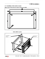
Страница 15: ...nstallation 15 32 3 DRO installation 3 1 Installation of the built in model Dimensions of the enclosure hole for inserting the DRO Built in DRO insertion Bolt ISO 7380 M4 x 10 Inox Nut DIN 985 M4 Inox...

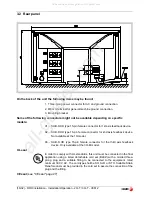
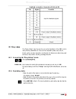
Страница 16: ...or 2nd axis feedback device Not available at the 10i model X3 SUB D HD type 15 pin female connector for the third axis feedback device Only available at the 30i M model UL seal In order to comply with...

Страница 17: ...F The storage temperature inside the DRO enclosure must be 25 C and 70 C 13 F and 158 F Maximum relative humidity 95 non condensing at 45 C 113 F Front Panel Sealing IP54 DIN 40050 Rear panel IP4X DI...

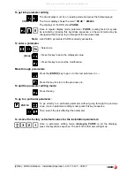
Страница 18: ...meaning that the feedback is not set up yet 3 5 2 Operating mode Move the axis to the origin or zero point and press the axis key The display shows START Move the axis in the positive direction all t...

Страница 19: ...to configure it for a particular application The way these parameters are displayed depends on whether they are general or particular for each axis If it affects the axes the parameter number PAR app...

Страница 20: ...key to save the displayed value Press this key to cancel the modification Move through parameters Press the ENTER key to go on to the next parameter or Press this key to return to the previous one To...

Страница 21: ...m 1 inches Note These units refer to feedback pulses not to the position display 4 Type of axis They must be set to zero 3 Not being used at this time 2 Not being used it must be set to 0 1 Counting d...

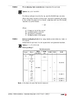
Страница 22: ...f the encoder P Leadscrew pitch in mm turn R Resolution in mm pulse F Multiplying factor to be applied PAR03 External multiplying factor when using distance coded reference marks or TTL signals Indepe...

Страница 23: ...d by the linear encoder 0 No 1 Yes 2 Detect travel limits PAR12 and PAR13 When this alarm is activated the axis value blinks The blinking axis error is cleared by returning the axis within its limits...

Страница 24: ...s the axis key It may toggle from absolute reading mode to incremental This parameter determines whether this toggle affects one axis or both Factory setting 1 PAR12 PAR13 Travel limit To set the nega...

Страница 25: ...To use this compensation it is recommended to set PAR 14 so as to force a mandatory home search on power up The compensation point must have at least one point with no error error 0 Multi point leadsc...

Страница 26: ...es Pressing any key or moving any of the axes turns the displays back on 6 1 Not being used at this time They must be set to 0 PAR53 Select the number of decimals to be displayed Possible values 0 0 t...

Страница 27: ...hines ELECTROMAGNETIC COMPATIBILITY EN 61000 6 4 Emission EN 55011 Radiated Class A Group 1 EN 55011 Conducted Class A Group 1 EN 61000 3 2 Harmonics EN 61000 3 3 Flickers EN 61000 6 2 Immunity EN 610...

Страница 28: ...cal discharges and fire hazards do not apply electrical voltage outside the range indicated in chapter 2 of this manual Ground connection In order to avoid electrical discharges connect the ground ter...

Страница 29: ...ected to the same AC power line as this equipment Nearby portable transmitters Radio telephones Ham radio transmitters Nearby radio TC transmitters Nearby arc welding machines Nearby High Voltage powe...

Страница 30: ...ipulated by personnel authorized by FAGOR If once the service call or repair has been completed the cause of the failure is not to be blamed the FAGOR product the customer must cover all generated exp...

Страница 31: ...there are OK disconnect the feedback connectors one by one If the dro comes on it means a feedback failure If the fault persists get in touch with Fagor Automation s Customer Services Department about...

Страница 32: ...the equipment is made with Do not use high pressure compressed air to clean the item as this could give rise to an accumulation of charges which in turn lead to electrostatic discharges The plastics...

Отзывы: