(26/32) - DRO installation - Installation/Operation - 20i-T / 30i-T - V0612
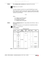
Select the desired axis and enter the number of points to be used for the axis,
up to 40. Zero means that there is no compensation table for the axis.
Where “
POS 1
” is the point number to enter and “
ERROR 1
” the amount of
error to be compensated.
Pressing [
ENTER
] displays the position value (X axis display) and the amount
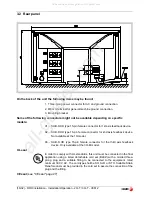
of error to be compensated (Z axis display).
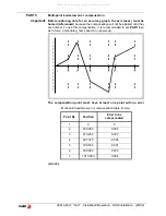
Error to be compensated = Master's actual position - displayed position
It goes on to edit the next point.
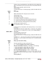
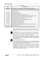
PAR20
It sets the configuration of the axes.
Digit
8
Turn the feedback off after 2 minutes in
"DISPLAY OFF"
mode.
7
The displays turn off if none of the axis has moved in 30 minutes. Pressing
any key or moving any of the axes turns the displays back on.
6 - 1
Not being used at this time. They must be set to “0”
PAR53
Select the number of decimals to be displayed.
Possible values:
0.0 to 6.6 .
The first digit corresponds to the number of decimals to be displayed in mm
and the second digit to the number of decimals in inches.
When selecting a “0” value or a value greater than the number of decimals of
PAR01
it will display the factory set number of decimals.
Note:
It has no effect on rotary axes.
PAR65
It enables various functions of the dro.
Digit
8, 7, 6
Not being used at this time.
5
1= To directly access parameter PAR05.
4
Not being used at this time.
3
1 = Enables the buzzer. It beeps when pressing any key.
2
To access the special functions (Hold, taper calculation)
1
It enables this key.
or
POS 1
ERROR 1
[Pos Nr]
[Error]
All manuals and user guides at all-guides.com
all-guides.com

