V0612-20i-T / 30i-T - Installation/Operation - DRO installation - (17/32)
WARNING
Do not handle the connectors while the unit is under power.
Before handling the connectors (mains, feedback, etc.) make sure that the
unit is not under power.
It is NOT enough to turn the display off by using the [on/off] key at the
keyboard
3.3 General technical characteristics
• Universal Power Supply between 100V AC and 240V AC ±10% at Mains
frequency between 45 Hz and 400 Hz. Between 120Vdc and 300 Vdc
• It withstands power outages of up to 20 milliseconds.
• 10-year memory backup of installation parameters when the unit is off.
• The operating temperature inside the DRO enclosure must be between 5º C
and 45º C (41ºF and 113ºF).
• The storage temperature inside the DRO enclosure must be -25º C and
+70º C (-13º F and 158º F).
• Maximum relative humidity: 95% non condensing at 45ºC (113ºF).
• Front Panel Sealing: IP54 (DIN 40050), Rear panel: IP4X (DIN40050)
except for built-in models in which case is: IP20.
3.4 Connections
3.4.1 Connection of the feedback systems
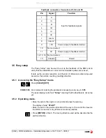
The feedback systems (linear or rotary encoders) are connected via SUB-D
HD type 15-pin female connectors: X1 through X3. The latter (for the 2nd
axis) is not available at the 10i model.
Characteristics of feedback inputs: X1, X2 and X3:
- Power consumption: 250 mA at the +5V input.
- Admits square-wave signal (TTL). (A, B, Io)
- Maximum frequency: 250 KHz, minimum gap between flanks: 950 nsec.
- Phase shift: 90º ±20º, hysteresis: 0.25 V, Vmax: 7V,
maximum input current: 3mA
- High threshold (logic state 1) 2.4V < VIH < 5V
- Low threshold (logic state 0) 0.0V < VIL < 0.55V
1
All manuals and user guides at all-guides.com

