


5
ELECTRICAL INSTALLATION
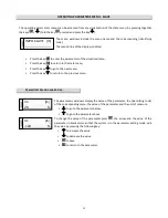
Loosen the screws and remove the cover completely before performing wiring. Connect the power wires and ground
to the appropriate regulator terminals. Custom (+SE) Controls with ground conductor section less 10mmq require
double earthing connection obtainable through the grounding of the aluminum heatsink. To avoid dispersion
currents, the motor earth cable must be connected to the appropriate motor terminal ground. We recommend to
connect to the machine’s safety circuit any thermal motor protector in order to remove the control power supply
and protect the motor with maximum efficiency. The thermal motor protector may be otherwise connected directly
to the I4 control card’s terminal. If the length of the motor cable exceeds 10 metres, we suggest to use shielded
cable. The control load (min. current out >200mA) can consist of several engines provided the sum of the rated
currents of the motors is less than 20% of the rated current of the control. We recommend not introduce any
electromechanical device on the motor cable. If the control cable length exceeds 3 metres, we suggest to use
shielded cable, connecting the shield only on the regulator. We suggest don’t connect the control 0volt to the earth.
If the length of the power, motor and control cables exceeds 10m, make sure they are separated by at least 0.3
metres to avoid creating a coupling effect.
If controls are set up in environment subject to electromagnetic disturbance, they should be housed inside a suitable
metallic enclosure. In order to prevent the formation of condensation and regular working also cold temperature it is
recommended you insure a constant power supply, avoiding turning it off continually.
All connections wires must resist to a 80°C working temperature.
Avoid routing any electric wires near the copper coils of the filter, use the suitable plastic
support ! Tighten all wires on control and power terminal boards fully down, avoiding
protrusion of the multi-stranded wire.
Do NOT touch the electronic equipment when the power line is on !
During voltage insulation tests disconnect the regulator power lines In/Out.
Use a true RMS tester to measure the current or voltage values.
The cover must be closed by screwing the screws with a torque of 1.2 Nm.
In the event that regulator operation failure could cause damage to objects or physical
injury, it is the responsability of the installer to add devises or systems that protect against,
or warn of, control failure.
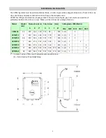
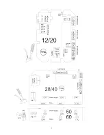
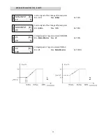
Check the position of the voltage change jumper according to the
supply voltage available, to the type of control (see coding
paragraph page 3, pos.3) and to the panoramic view of the
corresponding card.
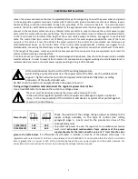
To protect the power line and the regulator, the installation technician
must install
extra-rapid semiconductor fuses upstream of the power
supply adequate for the load and with a value of I ² t less than the value
given in the table below
. If a differential circuit breaker is installed, it must be of the delayed action type.
The
regulators with rated current > 16A are in accordance to the IEC61000-3-12 on condition that the short circuit ratio
Rsce is greater than or equal to 120 at the interface between the user power supply and the public network. For
values Rsce minor can reduce harmonics by increasing the voltage/minimum speed.
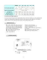
Power Supply
C (230/400V)
230
400
D (440/460V)
440
460


