


9
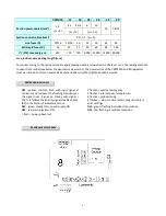
CONTROL PANEL
The control panel visualizes in real time the inputs and outputs of the adjuster and allows to set the parameters. It
is provided with a back-illuminated LCD/OLED display and with four keys described below.
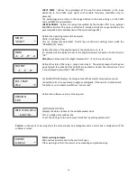
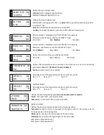
STATE MENU
After the device is powered the display visualizes the firmware versions of the adjuster and the keyboard. Then, if
no error occurs, appears the first
state window
which visualizes the temperature or the pressure registered by
input 1:
RUN
in operating state
FLT
in block state
RDY
if in Stop state
The cycle used for the adjusting is visualized at the right bottom: CO (COOL) or HEA (HEAT) followed by the
number 1 or 2 for first or second cycle.
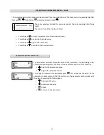
In this mode:
•
Press the key
to slide the state menu downward;
•
Press the key
to slide the state menu upward.
S
TATE WINDOW BOXES
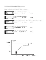
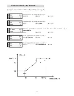
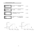
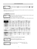
Defines the output voltage/speed. The percentage value refers from 0 to 98% of power
voltage.
INPUT 1
: Defines the percentage of the IN1 input among the following possible
signals: 0..10V=, 4..20mA, pwm (100Hz type with variable average value).
Goes to the next
visualization / decreases a
parameter
Goes to the previous
visualization /
increases a parameter
Enters the menu and the
parameters / confirms the
variation of a parameter
parametro
Escapes from the menu and
the parameters / cancels a
variation of parameter
OUTPUT
67
%
D
R
Y
C
O
O
LE
R
Temp.1
21.3 °C
[CO1]
[RUN]
C
H
IL
LE
R
Press.1
20.3 bar
[CO1]
[RUN]
23
INPUT
%
S
LA
V
E


