


20
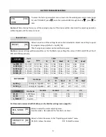
SPEED LIMITS
This function is usally used to set a reduced maximum speed in the night to reduce the noise or a fixed speed
detached from the probe signals.
Caution : With the I2 digital input closed (the clock can be used optionally) this function automatically enables the
speed limit values (V1 and V2 Limit) on all the Master operating cycles (CHILLER and DRY COOLER) and the dispaly
visualizes
.
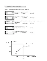
Voltage that replaces V1, in the
Master
cycle used, when the I2 max production contact
is closed.
Voltage that replaces V1, in the
Slave
cycle, when V1 LIMIT>V1.
Min.
MotorMinLim
Max.
V2 Limit
Def. 18%
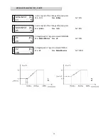
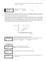
Frost protection function:
COOL cycle: For V1 Limit > V1 of the active cycle, if the pressure/temperature is lower than P1/T1, the Voltage OUT
(Vout%) will be fixed at the value of the V1 Limit (see for example the below chart 2).
HEAT cycle: For V1 Limit > V1 of the active cycle, if the pressure/temperature is higher than P2/T2, the voltage OUT
(Vout%) will be fixed at the value of the V1 Limit (see for example the below chart 4).
With S1 additional card and ambient probe connected, the above is valid for both cycles as long as the ambient
temperature is lower than 3 ° C.
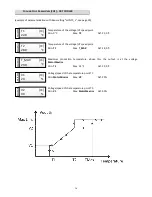
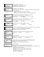
Voltage that replaces V2, in the Master cycle used, when the max productions
I2 contact
is closed.
Min.
V1 Limit
Max.
MotorMaxLim
Def. 65%
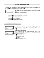
[WITH CLOCK OPTION]
Allows to enable the V1 and V2 limits in the Master operating cycles, not only by closing
the I2 contact, but also through the timer calendar set in the Clock menu (page 6). Def.
OFF
65
V2 LIMIT
[LV]
%
Off
ENAB W/TIME
[LV]
*
18
V1 LIMIT
[LV]
%


