


8
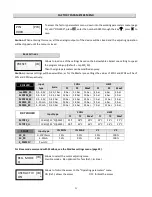
CONTROLS TERMINAL BOARD
Term.
Description
Application
Page
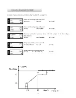
T1+
Serial RS485, Modbus RTU - Slave
T1 -
Serial RS485, Modbus RTU - Slave
Serial connection line to a Master controlled device
25
0V
Ground I/O
Mass I/O
IF
IF
Pwm FV, 2..20kHz input (Ri =500Ω, 5..24V))
Variable frequency command for mode slave
running
22
I 4
External emergency input
Open immediately blocks the control. It can be
connected to the load temp. protecting device/s
I 3
Start/Stop input
Programmable Start/Stop input
23
I 2
Limit Speed function input
Closed modifies the adjusting modes. It is often
used for the night silenced operating
20
I 1
Direct/Reverse function input
Open enables the Cool1 cooling mode. Closed
enables the Heat or Cool2 heating mode (to be set
on basic sett. menu)
22
0V
Ground I/O
Mass for the digital inputs
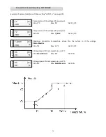
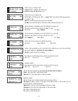
0.10
Analog input , type 0.10V (Ri = 40k Ω)
0..10V command for mode slave running
22
+V
12V power supply output = (max 30mA)
4..20mA pressure transducer power supply
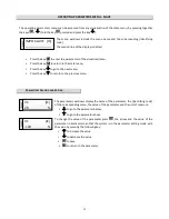
NC
Relay 1 closed norm. contact output
COM
Relay 1 common contact output
(1A-250V~/3A-30V=)
NO
Relay 1 open norm. contact output
Programmable output. With standard setting for
Defect, the relay is enabled (NO-COM eachother
closed) and is disabled by turning to the position
represented in the picture in emergency case.
24
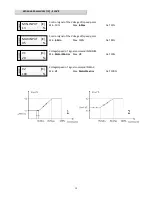
+5V
5V power supply output = (max 15mA)
Ratiometric press. transd. and NTC power supply
IN 1
Analogical input 1, type 0,5…4,5V / ntc
(10 kΩ @25°C, β3435), (Ri = 10 kΩ) / pwm 5..15V
Ratiometric pressure transducers / NTC sensor /
Pwm 100Hz type with variable average value
21-22
0V
Ground I/O
Mass for analogical input
4.20
Analogical input 1, type 4…20mA (Ri = 100 Ω)
4..20mA pressure transducers input,command for
mode slave running
21-21


