


24
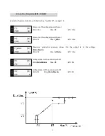
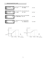
Higher voltage of the jump window.
Min.
Sup.Min.Lim.1
Max.
Sup.Min.Lim.2
Def. 30%
(this parameter is visualized only if “Suppress.1” is ON).
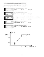
The functions “
Suppress.2
” and “
Suppress.3
” with corresponding limits operate alike the “
Suppress 1
” and are
prioritary functions on any operating cycle.
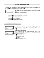
R
ELAY
S
ETTINGS
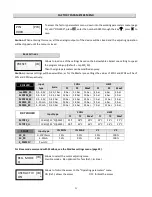
Enables the internal relay based on the following settings:
Default (Def.)
: enabled relay in a condition of regular operating, disabled relay in
emergency case (see image page 9)
Hysteresis
: This function, for “Chiller mode” and “Dry cooler mode”, is used for the control of solenoid valves/
sprayers. Relay enabled above the Lim.max.relay value and disabled under the Lim.min.relay value. The Lim.max
parameters. and lim.min. are expressed in ° C or bar depending on the setting. They are displayed only when "relay"
is set to "hysteresis."
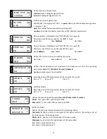
[WITH CARD S1]
The relay exchange in relation to the priority probe.
WARNING : This function, if used with ambient temperature sensor, expects a temperature threshold (Default 10°C)
below which the relay will not be excited. See section “Advanced Settings – T° Limit” for modify the value.
Load
Partialization
[WITH CARD S1 and AMBIENT PROBE CONNECTED]:
This feature, for “Chiller mode” and “Dry cooler mode”, allows you to split the load in 2 or 3 subgroups connected
to the power out through two contactors KM1 and KM2 (Class AC-2) respectively controlled by relay R2 and R3 of S1
card.
30
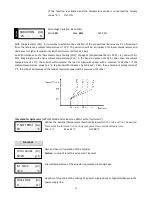
SUP.MAX.LIM.1 [IM]
%
default
RELAY
[IR]
*


