Version 07/11- Page 9
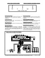
Rangehood Control Panel
The control panel is located on the side front of the canopy. The
position and function of each control button are noted below
(FIGURE 12)
.
Light On/Off Button ( L )
On/Off switch for the halogen lights. Press the light button to turn
the light ON. and again to turn off.
Blower Off Button ( M )
Off switch for the blower. The blower can be operated by pressing
any of the speed buttons
Blower Speed Button ( V )
Speed control for blower.
Press the switch "1" for LOW speed,
"2" for MEDIUM speed and "3" for HIGH speed. Hold down the
speed 3 button for 5 seconds to activate the intensive speed. Which
operates the hood for 10 minutes on the high speed and then returns
the previous speed.
WIRING DIAGRAM FOR
3-SPEED 600 CFM MODEL
DIAGRAMME DE CÂBLAGE MOD
È
LE 3 VITESSE 600 PCM
• This rangehood uses 20 watt Halogen Lamps. / Cette hotte utilise les ampoule halogènes de 20 W.
CONTROL PANELS AND WIRING DIAGRAMS
PANNEAU DE COMMANDES & DIAGRAMMES DE CÂBLAGE
Panneau de commandes
Le panneau de commandes est situé sur le moyen sous la hotte.
La position et la fonction de chaque bouton sont indiquées à la
(
FIGURE 12
)
Bouton marche-arrêt de la lumière (L)
Interrupteur marche-arrêt pour la lumière. Régler à « 1 » pour mettre
en circuit (ON) et à « 0 » pour mettre hors circuit (OFF).
Ventilateur outre de bouton (M)
Outre du commutateur pour le ventilateur. Le ventilateur peut être
actionné en appuyant sur les boutons l'uns des de vitesse
Bouton de vitesse du ventilateur (V)
Commande de vitesse pour le ventilateur. Pressez le " de
commutateur ; 1" ; pour à vitesse réduite, " ; 2" ; pour la vitesse
MOYENNE et le " ; 3" ; pour la vitesse. Maintenez le bouton de
la vitesse 3 pendant 5 secondes pour activer la vitesse intensive.
Ce qui fonctionne le capot pendant 10 minutes sur la vitesse et
renvoie alors la vitesse précédente.
L
M
V
0
1
2
3
4
5
6
7
8
9
Creato da.
Rev :
Ver :
DOLCE CORRADO
Materiali: non deveno contenere Pb, Cr6+, Hg, PBB, pbde, ai sensi della direttiva 2002/95 CE
SCHEMA ELETTRICO M8-4V ESB FARETTI
Non rilevare quote dal grafico non apportare modifiche senza l'autorizzazione d'ufficio progettazione
a termini di legge ci riserviamo la proprieta' del presente disegno con divieto di riproduzione totale o parziale
Code :
Disegno N :
Data:
08.Set.2010
LINE IN
120Vac
60Hz ~
L
N
Y-G
WIRING BOX
BLU
RED
BLK
WHT
Y-G
1
2
3
4
5
6
BLK
V1
MC
F
V2
ESB
0
MOTOR
1
MOTOR
BR
W
G
R
Y
BL
U
1
2
3
6
5
4
7
8
9
1
2
3
6
5
4
9
8
7
RED
M8 4V
120V ~
W
H
T
BRW
2
SPEED
BL
U
BL
K
1
1
BL
K
BL
K
W
H
T
2
2
W
H
T
O
R
G
BR
W
3
3
BR
W
G
R
Y
4
4
G
R
Y
RED
WHT
BLU
Y-
G
BL
U
5
5
BL
U
3/I
SPEED
R
ED
6
6
R
ED
W
H
T
7
7
W
H
T
VL
T(
O
R
G
)
8
8
VL
T(
O
R
G
)
R
ED
(O
R
G
)
9
9
R
ED
(O
R
G
)
R
ED
10
10
R
ED
VL
T
11
11
VL
T
0-1
LIGHT
12
12
TOROIDAL
TRANSFORMER
W
H
T
4
3
BL
K
RED
2
1
BL
K
N
L
V4
L
V3
O
R
G
2
1
R
ED
O
R
G
4
3
VL
T
WHT
1
2
3
4
5
6
O
R
G
WHT
BRW
GRY
O
R
G
RED(ORG)
VLT(ORG)
R
ED VL
T
PRI.
SEC.
ELECTRONIC
TRNSFORMER
VL
T
R
ED
HALOGEN
LAMPS
VL
T
INCANDESCENT
LAMP
R
ED
HALOGEN
LAMPS
HALOGEN
LAMPS
HALOGEN
LAMPS
FIGURE 12 - 3-SPEED /
3 VITESSE


