background image

4

ELECTRICAL REQUIREMENTS

A 120 volt, 60 Hz AC-only electrical supply is required on a separate 15 amp fused circuit.  A time-delay 

fuse or circuit breaker is recommended.  The fuse must be sized per local codes in accordance with 

the electrical rating of this unit as specified on the serial/rating plate located inside the unit near the field 

wiring compartment. 

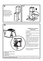
ELECTRICAL  INSTALLATION WITH WIRING BOX

THIS UNIT MUST BE CONNECTED WITH COPPER WIRE ONLY.  Wire sizes must conform to the 

requirements of the National Electrical Code, ANSI/NFPA 70 - latest edition, and all local codes and 

ordinances.  Wire size and connections must conform with the rating of the appliance.  Copies of the 

standard listed above may be obtained from: 


National Fire Protection Association


Batterymarch Park


Quincy, Massachusetts  02269

This appliance should be connected directly to the fused disconnect (or circuit breaker) through 

flexible, armored or nonmetallic sheathed copper cable.  Allow some slack in the cable so the 

appliance can be moved if servicing is ever necessary.  A UL Listed, 1/2" conduit connector must 

be provided at each end of the power supply cable (at the appliance and at the junction box). 

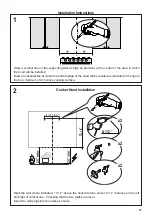
When making the electrical connection, cut a 1 1/4" hole in the wall.  A hole cut through wood 

must be sanded until smooth.  A hole through metal must have a grommet. 

• Electrical ground is required on this rangehood.

• If cold water pipe is interrupted by plastic, nonmetallic gaskets or other materials, DO 

NOT use for grounding.

• DO NOT ground to a gas pipe.

• DO NOT have a fuse in the neutral or grounding circuit.  A fuse in the neutral or 

grounding circuit could result in electrical shock.

• Check with a qualified electrician if you are in doubt as to whether the rangehood is 

properly grounded. 

• Failure to follow electrical requirements may result in a fire.   

   WARNING

!

Содержание CTAL31BK300-B

Страница 1: ...CTAL31BK300 B CTAL36BK300 B Installation Instructions Use and Care Information Instructions d installation Utilisez et d entretien COCKTAIL...

Страница 2: ...with your back to an exit Based on Kitchen Firesafety Tips published by NFPA WARNING TO REDUCE THE RISK OF FIRE OR ELECTRIC SHOCK do not use this fan with any solid state speed control device WARNING...

Страница 3: ...o minimize conduction of outside temperatures as part of the vent system The damper should be on the cold air side of the thermal break The break should be as close as possible to where the vent syste...

Страница 4: ...ld be connected directly to the fused disconnect or circuit breaker through flexible armored or nonmetallic sheathed copper cable Allow some slack in the cable so the appliance can be moved if servici...

Страница 5: ...5 RANGEHOOD DIMENSIONS ELECTRICAL CONNECTION KNOCKOUT...

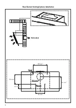
Страница 6: ...6 Min 21 3 16 Min 24...

Страница 7: ...ion Components 7 2 1 2 OptionalUpperChimneySection Fixing Brackets 11b 2 Wall Plug 12a 4 Screws 3 16 x 1 3 4 12b 2 Screws 1 8 x 3 8 12c 4 Screws 1 8 x 1 4 12d 2 Screws 1 8 x 3 8 12e 4 Screws 1 8 x 1 4...

Страница 8: ...Requires purchase of Activated Charcoal Accessory Horizontal Vertical 6 I Install Damper that is included with the Hood before connecting to the ductwork Only for Ducted Venting Installation When used...

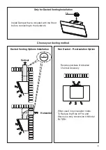
Страница 9: ...9 Rear Ducted Venting Options Installation Horizontal...

Страница 10: ...e four screws from each cover plate as shownandtakeoffthecoverplates Donotdiscard and set aside for future use Disconnect the Connector from the blower Unscrew the 2 screws that hold the blower and un...

Страница 11: ...cted Venting Options Installation A7 H 2x A10 H 2x After removing blower rotate as shown untilitisinthecorrectrearventingposition Usethetwoscrewsthatwereremovedto secure the blower as shown in Image B...

Страница 12: ...ottom edge of the hood will be located as indicated in the figure that is a minimum of 24 above cooking surface Mark the wall where indicated 13 1 4 above the horizontal line and at 6 7 16 distance on...

Страница 13: ...levertowardstheback of the unit and at the same time pulling downward 3 Screw the filter cover onto the air outlet using four screws 12e Fix the directional Grid on the recycled air outlet using 2 scr...

Страница 14: ...oles Using two remaining screws to anchor the hood in holes 5 16 8 9 Drill directly into 5 16 holes at all the center points marked 6 Hook the hood body onto the wall 7 From the inside of the hood bod...

Страница 15: ...the center notch withtheverticalreferencelineandmarkthewallatthecentersoftheholesinthebracket Place the second bracket 7 2 1 on the wall as shown below the first bracket at the height of the upper ch...

Страница 16: ...ed previously to secure the angle bracket included with Optional Tele scopic Chimney Kit Install Roof or Wall Cap purchased separately Con nect the 6 metal ductwork to the Roof or Wall Cap and then at...

Страница 17: ...Installation of wiring connection Remove the cover from the field wiring compartment DO NOT turn on the power until installa tion is complete Connect the Power Supply Cable to the rangehood Connect t...

Страница 18: ...ed separately Attach each charcoal filter to the black grid on each side of the blower Press the charcoal filter tightly to the black grid on the blower side and rotate the filter clockwise towards th...

Страница 19: ...s Buttons High Speed Intensive Speed Hold down the button for 2 seconds to activate the INTENSIVE SPEED which is timed to run for 6 minutes At the end of this time it will automatically return to the...

Страница 20: ...of the filter changes color over time this will have absolutely no effect on its efficiency Replace taking care to ensure that the handle faces forward Cleaning in dishwasher may dull the finish of t...

Страница 21: ...21 Wiring Diagram...

Страница 22: ...om accident alteration misuse abuse fire flood acts of God improper installation installation not in accordance with electrical or plumbing codes or Faber documentation or use of products not approved...

Страница 23: ...nevoiedesortiesetrouvederri revouspendantquevous teignezlesflammes D apr sleguide KitchenFiresafetyTips publi parlaNFPAaux tats Unis AVERTISSEMENT POURR DUIRELERISQUED INCENDIEOUDECHOC LECTRIQUE n uti...

Страница 24: ...ation doit pr voir un registre antirefoulement suppl mentaire pour r duire le flux d air froid inverse ainsi qu une barri re thermique non m tallique pour r duire la conduction destemp raturesext rieu...

Страница 25: ...u sectionneur fusible ou au disjoncteur par un c ble flexible de cuivre avec blindage ou gaine non m tallique Laissez un peu de jeu dans le c ble pour permettre le d placement de l appareil si des tra...

Страница 26: ...26 DIMENSIONS DE LA HOTTE DIMENSION L ENTR E LECTRIQUE D FON ABLE...

Страница 27: ...27 Min 24 Min 24...

Страница 28: ...es filtres ventilateur 2 1 Chemin et lescopiquecomprenant Achet s par ment 2 1 1 Sectionsup rieureoptionnel 2 2 1 Sectioninf rieureoptionnel 3 1 Grille orient e Sortie de l Air 4 1 Couvercle filtrant...

Страница 29: ...ment Choisissez la m thode de canalisation Sans canalisation Option de recirculation Options d installation avec ventilation canalis e Exige l achat de l accessoire charbon actif Horizontale Verticale...

Страница 30: ...30 Horizontale Options d installation avec ventilation canalis e vers l arri re...

Страница 31: ...plaques deprotectioncommeillustr etretirezlesquatre plaques de protection Ne les jetez pas gardez les pour utilisation ult rieure D branchez le connecteur du ventilateur D vissezles2visquiretiennentl...

Страница 32: ...canalis e vers l arri re Apr s avoir enlev le ventilateur faites tourner comme illustr jusqu atteindre la position correcte pour la ventilation vers l arri re Utilisez les deux vis enlev es pr c demme...

Страница 33: ...e la hotte comme repr sent dans l illustration Cet emplacement doit se trouver au moins 24 de la surface de cuisson Notice d installation Cooker Hood Installation Tracez un rep re sur le mur l endroit...

Страница 34: ...quatre vis 12d Fixer la grille orient e 8 sur la sortie de l air recycl avec 2 vis 12e Ouvrezlepanneau Retirezlefiltre enpoussantsimultan mentlelevier vers l arri re de l appareil et en le tirant vers...

Страница 35: ...2 barres Agir sur les vis de l int rieur du corps de hotte pour en r gler le niveau Ins rez les chevilles achet es dans les trous Utilisez les deux vis restantes pour ancrer la hotte aux trous Percez...

Страница 36: ...du plafond ou de la limite sup rieure en alignant le centre encoche avec la ligne de r f rence verticale Marquez l emplacement du centre des trous du support sur le mur Placez la deuxi me bride 7 2 1...

Страница 37: ...pour visser l querre de fixation comprise dans la trousse de chemi n e t lescopique en option Installez le clapet de toiture ou le cla pet mural achet s par ment Rac cordez le conduit m tallique de 6...

Страница 38: ...le fil vert vert et jaune de mise la terre sous la vis de mise la terre verte Branchez le fil blanc de l alimentation au fil blanc de la hotte l aide d un connecteur verrouill par rotation Branchez l...

Страница 39: ...rmement le filtre charbon contre la grille noire de chaque c t du ventilateur et faites tourner le filtre dans le sens des aiguilles d une montre vers l avant de la hotte jusqu ce qu il soit verrouill...

Страница 40: ...T2 Boutons de r glage du ventilateur vitesse r duite T3 Boutons de r glage du ventilateur vitesse moyenne Tenez ce bouton enfonc pendant 2 secondes pour activer la fonction de d sactivation retard e q...

Страница 41: ...la surface du filtre au fil du temps n a aucun impact sur son efficacit Remettez leenplace envousassurantque la poign e se trouve vers l avant Lelave vaissellepourraitternirlefinidufiltre graisse m ta...

Страница 42: ...42 Sch ma de c blage...

Страница 43: ...es d coulant d un accident d une modification de l utilisation incorrecte ou abusive d un incendie d une inondation d un cas de force majeure d une installation inad quate d une installation non confo...

Страница 44: ...991 0473 136_05 180309 D003060_04...

Отзывы: