Page G-2
MOTOR & MOTOR BRAKE
Repair and Service Manual
Read all of Section B and this section before attempting any procedure. Pay particular attention to all Notes, Cautions and Warnings.
B
.
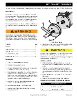
Fig. 2 Motor Connections
10. Pull the motor wires out through the bagwell.
11. Remove the six hex head bolts (2) and split lock wash-
ers (3) securing the motor (1) to the axle and carefully
slide the motor straight out from the axle splines.
Note: a drive belt or woven strap may be used as a
sling to help support the motor during removal.
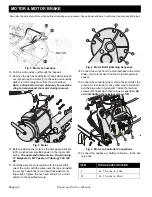
Fig. 3 Motor
12. Before installing the motor on the axle apply lubricant
(80% molybdenum disulfide paste) to the input shaft
spline.
The approved lubricants are: Dow Corning
77, Molykote (r) M-77 paste or Tribology TAS 100
EP
13. Carefully align the motor spline with the input shaft,
orient the motor with the wires near the top and install
the six hex head bolts (2) and split lock washers (3)
finger tight. Tighten the hex head bolts (2) in a cross
pattern to the specified torque.
Fig. 4 Motor Bolt Tightening Sequence
14. Connect the wires from the main harness to the motor
brake, the motor sensor and the motor temperature
sensor.
15. Connect the wires from the motor to the controller; the
green wire to terminal U, the yellow wire to terminal V
and the blue wire to terminal W. Install the terminal
screws (27) finger tight, then torque as specified.
Do
not over tighten the terminal screws (27).
.
Fig. 5 Motor to Controller Connections
16. Connect the negative (-) battery cable, BL-, to the bat-
tery pack.
MOTOR
ITEM
TORQUE SPECIFICATION
2
53 - 79 in. lbs (6 - 9 Nm)
27
53 - 71 in. lbs (6 - 8Nm)

