ELECTRICAL COMPONENTS & WIRING
Page K-15
Repair and Service Manual
Read all of Section B and this section before attempting any procedure. Pay particular attention to all Notes, Cautions and Warnings.
B
B
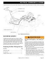
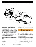
the vehicle and secure in place with the hex head bolt.
4. Connect the accessory wire harness to the horn.
State of Charge / Fuel Gauge Replace-
ment
Tool List
Qty.
Torx Bit 27 IP ............................................................... 1
Ratchet........................................................................ 1
Make sure that the vehicle key switch is in the ’OFF’
position and the key has been removed.
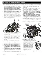
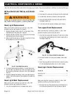
1. Remove the four Torx head screws (10) that secure
the instrument panel trim (11) to the instrument panel.
Fig. 28 Trim Panel Hardware
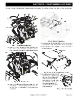
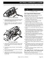
2. Pull the top of the trim panel (11) away from the instru-
ment panel and disconnect the harness (21) from the
fuel gauge/state of charge meter (20).
3. Depress the tabs on the fuel gage/state of charge
meter (20) and push the unit out of the trim panel (11).
Fig. 29 Fuel Gage/State of Charge Meter
4. Insert the new fuel gage/state of charge meter (20)
into the opening in the instrument panel trim (11),
making sure that the tabs all lock in place.
5. Connect the accessory harness (21) to the fuel gage/
state of charge meter (20)
6. Push the instrument panel trim (11) into place making
sure that no wires are pinched.
7. Install the four Torx head screws (10) that secure the
instrument panel trim (11) to the instrument panel and
the front cowl.
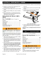
ITEM
TORQUE SPECIFICATION
10
6- 9 ft. lbs (8 - 127 Nm)

