User Manual
Version 1.2 (October 2018)
Technical changes reserved.
ec
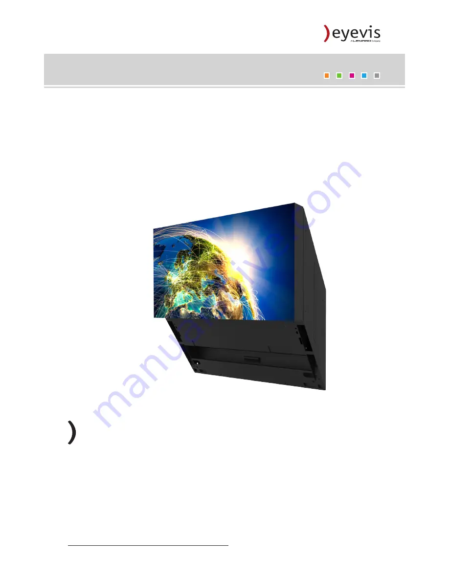
CUBE®-LED-SLIM Series
EYEVIS REAR PROJECTOR LINE
Страница 1: ...User Manual Version 1 2 October 2018 Technical changes reserved ecCUBE LED SLIM Series EYEVIS REAR PROJECTOR LINE...
Страница 2: ...part of this documentation may be reproduced stored in databases or transferred in any form electronically mechanically on recording media or in any other way without prior written consent of eyevis...
Страница 3: ...g the cubes Cube ID 39 Rotation switches 39 Setting up network communication 40 Network settings for the PC 40 Front access optional 41 Tools 41 Open the front access mechanism 41 Adjusting the geomet...
Страница 4: ...d by warranty defects 54 Legal and other claims 54 Limitations of liability 55 Appendix 56 Appendix Technical Specifications 56 Environmental 56 Appendix Technical Specifications 57 EC 50 LHD ISE SLIM...
Страница 5: ...schriebenen Warnstufen verwendet VORSICHT Kennzeichnet eine Gefahr die zu leichten oder mittleren Verletzungen f hren kann WARNUNG Kennzeichnet eine Gefahr die zum Tod oder zu schweren Verletzungen f...
Страница 6: ...n dieser Bedienungsanleitung Beachten Sie unbedingt alle Anweisungen zum Betrieb und Nutzung unserer Systeme Beachten Sie alle lokalen Vorschriften zum Aufbau und Betrieb von Anlagen unter die unsere...
Страница 7: ...igkeit Halten Sie die L ftungs ffnungen des Ger ts offen Stecken Sie das Netzkabel erst am Ger t ein bevor Sie es in die Steckdose stecken und verlegen Sie das Netzkabel so dass niemand dar ber stolpe...
Страница 8: ...Datenl schung die durch die Verwendung von eyevis Produkten bzw deren Ausfall im Betrieb verursacht werden eyevis ist nicht haftbar f r Sch den die in Folge mangelnder Beachtung der Anweisungen dieser...
Страница 9: ...junction with the warning levels described below CAUTION Indicates a hazard that could lead to minor or moderate injuries WARNING Indicates a hazard that could lead to death or serious injury DANGER I...
Страница 10: ...ions which our systems are subject too Power Only use the power cable supplied by eyevis The power cable must be correctly and securely connected to earthed power outlets Do not connect multiple devic...
Страница 11: ...the device before plugging it into the outlet and do not locate the device where persons may trip over the cable If an extension cable is necessary a cable with a current rating at least equal to that...
Страница 12: ...uption in business data modification or data deletion caused by the use of eyevis products or their operation failure eyevis is not liable for any damage caused by non compliance to the instructions d...
Страница 13: ...e design with integrated and motorized geometry adjustment enables a quick and easy setup Like all eyevis cubes the new slim model is equipped with a robust self supporting housing and the reliable se...
Страница 14: ...rwise this can result in injury and damage to the cube At least two people are needed to unpack the cube To unpack the projector 1 Remove the packing tape 2 Remove the top cover of the cardboard box 3...
Страница 15: ...1 N3 N4 N2 L2 I2 16x M8x25 2x 16x M8 4x 2x 2x 8x M10x25 2x 2x 10 2x M8 2x M6x25 2x M6x60 8x M12 8x M12 8x M6 washer DIN 125 A 2x A C D B E F 2x Side basements A Left side basement B Right side basemen...
Страница 16: ...fasten to the floor N3 4 hexagon wooden screws 4 M10 dowels 4 M8 washers I1 I3 L1 N1 N3 N4 N2 L2 I2 16x M8x25 2x 16x M8 4x 2x 2x 2x 2x 10 2x M8 2x M6x25 2x M6x60 8x M12 8x M12 8x M6 washer DIN 125 A...
Страница 17: ...ection and adjustment elements NOTE The illustrations and certain descriptions in this manual may vary due to development process Housing and backplane 1 3 2 Fig 1 Back view of cube interior 1 Mirror...
Страница 18: ...r NOTE The illustrations and certain descriptions in this manual may vary due to development process Fig 2 Front view of the projector 1 2 1 Optics 2 Control connector module EC LED SLIM Series 18 Use...
Страница 19: ...Fig 3 Rear view of the projector 6 4 5 4 Rotation Switch for projector addressing Stand by button 5 Projector earthing 6 Mains supply power switch EC LED SLIM Series 19 Version 1 2 October 2018...
Страница 20: ...ctors 1 RS232 OUT RJ45 2 RS232 IN RJ45 3 LAN RJ45 4 LEDs display status 5 DIP Switcher Service 6 DisplayPort 7 5V 1A max power output Mains supply 1 2 3 Fig 5 Mains supply 1 Power switcher On Off 2 Fu...
Страница 21: ...shed 4 Error State The error state LED indicates the error status During the initialization procedure the LED will blink together with the CPU state LED in the same frequency After the initialization...
Страница 22: ...Transport security 1 The projector is secured to the cube housing with 2 screws from the bottom side of the cube housing Take this 2 screws out so that you can take the projector out of the cube housi...
Страница 23: ...15 cm for adjusting the mirror of the projection cube WARNING If the video wall is higher than three metres it should be secured at the back to the building wall Please contact our project team for de...
Страница 24: ...le parts for mounting 2x A C D H L1 N2 N3 O2 O1 N1 L2 B 16x M8x25 8x M6x25 16x M8 4x 4x 10x M10x25 4x 4x 10 4x M8 8x M6 washer DIN 125 A 8x M12 8x M12 E F 2x Fig 12 A B D E 1 2 3 F C Mounting the base...
Страница 25: ...nting the cube housing Mounting the cube housing onto the basement 1 Place a housing onto the first basement 2 The basement and the cube must be at least connected together using the screws O1 and was...
Страница 26: ...mounted So first adjust the high of the UGV before starting with other steps First loosen and remove all 4 screws front and back side of each base completely to move the upper part of the base up or...
Страница 27: ...cube housing was mounted Than a stable stand is guaranteed and on the base is some pressure Connecting two bases If more than one cube housing will be used in a row the bases have to be connected on...
Страница 28: ...sing Alternatively you can mount the front screen to the basement and than put the housing on the basement Every additional cube housing can be equipped with one base and than mounted on the primary f...
Страница 29: ...all mount two cubes 1 Loosen both screws under the projector and then remove the projector 2 The top cover must be installed on the to cubes 3 Attach the wall mount to the wall The wall mount consists...
Страница 30: ...Fig 24 180mm thread bar with eyebolt Fig 25 150mm thread bar For bolting the cubes different thread bars are needed In the front top of the cube under the holder of the screen the shortest thread bars...
Страница 31: ...s must be secured with a screw on both sides The front covers of the bigger cubes have some additional butt straps Fig 26 Placing the front covers Fig 27 Cube housing with mounted front covers Alterna...
Страница 32: ...til it fits to the bolts Fig 29 Position bolts for the projector Fig 30 Inserting projector into cube 9 Install carefully the screens of the cubes The screens have to be clipped on the holder with the...
Страница 33: ...he brackets at first Fig 32 Installing cover brackets 2 Install the cover for the fresh air intake When you are in front of the cube the fresh air intake is on the right side When you are at the back...
Страница 34: ...all the lateral exhaust plate on the left side The exhaust plate is available in two versions a Exhaust plate Air grille b Exhaust plate for connection of an air conditioning optional Fig 35 Installin...
Страница 35: ...5 Install the side plate on the right side Fig 36 Installing side plate The installation is finished EC LED SLIM Series 35 Version 1 2 October 2018...
Страница 36: ...ft and right in each housing To connect the earthing cables 1 Guide the earthing cables through the circular openings and screw the cable eyelets with the prepared screw to the next housing 2 Connect...
Страница 37: ...daisy chain Proceed according to the following diagram Fig 38 1 2 3 4 5 6 7 8 9 Serial daisy chain cabling To connect the cubes to the control PC Connect the control PC RS232 OUT to projector 1 serial...
Страница 38: ...Chain between the projectors Fig 41 Slim cube housing On the side of the cube housing are square holes where the cables can be transferred to the next cube In the corners on the bottom side of the cub...
Страница 39: ...top left cube of the video wall and continues as shown in the diagram below 1 2 3 4 5 6 7 8 9 10 11 12 NOTE If you setup a cube video wall with wall mount installation and front access option the ID o...
Страница 40: ...ork settings for the PC 1 To configure the network settings for your network adapter open the preferences of your Internet Protocol Version 4 TCP IPv4 as shown below You can find the settings in the f...
Страница 41: ...ube wall with front access If more suction cups are needed then they can be ordered separately NOTICE Handling always with tools If the front access mechanism is used without the tools the screen of t...
Страница 42: ...3 Pull the screen toward you carefully Fig 44 Detail of the optics Fig 45 Detail of the optics 4 Lift the screen slightly and remove the screen carefully EC LED SLIM Series 42 User Manual...
Страница 43: ...d directory on your PC for example c Software 2 Open the file eyeDesign exe by double clicking to start the software Starting the software Open the eyeDESIGN software to configure the video wall The p...
Страница 44: ...e cube wall 3 Buttons ON and OFF Activates deactivates the function of engine control 4 Button STOP ALL Stops all engines instantly 5 Cube ID Selects the cube ID for adjustment 6 Duration Adjusts the...
Страница 45: ...Vertical image position Rotation Image size Vertical keystone Horizontal keystone NOTICE eyeDESIGN manual For more details about the eyeDESIGN software please refer the eyeDESIGN manual EC LED SLIM Se...
Страница 46: ...w will influence on a larger part of the mirror and is not locally restricted Fig 48 View on the mirror from front 1 5 2 6 3 7 4 8 Focus adjustment In order to achieve a clear picture on the projectio...
Страница 47: ...can damage the eyes Looking into the projector light for longer time during operation may be harmful for the eyes Do not look into the lamp for longer time during operation Fig 49 Detail of the optic...
Страница 48: ...is device and to protect it from damage WARNING Dangerous electric voltage inside the device Cleaning the device while connected to the power supply can result in death severe injury or can damage the...
Страница 49: ...y be damaged Cleaning the housing NOTICE Unsuitable cleaning substances Never use substances such as thinners benzene or abrasive cleaners They can damage the surface of the housing Cleaning sprays On...
Страница 50: ...ke sure that the signal is suitable Make sure that the DisplayPort signal not contains HDCP Make sure that the input signal resolution for the input box without scaler board is correct Blurred picture...
Страница 51: ...spilled or dropped this may cause a fire or an electric shock Immediately remove the power plug from the outlet Contact your dealer for inspection CAUTION Damage caused by dropping the device If you c...
Страница 52: ...otify his specialist supplier point of purchase immediately about the defect Otherwise the product will be treated under usual terms of warranty Return to Base Warranty Bring In Warranty Defective par...
Страница 53: ...rette smoke and dust Defects caused by normal wear and tear or defects caused by lack of service and maintenance e g cleaning the filter Act of God fire flood aggressive chemical aggressive biological...
Страница 54: ...tomer Packing The customer has to pack the defective device properly in the original box to label it as fragile and to attach the RMA number visibly on the box eyevis can provide a new original box on...
Страница 55: ...damage The policy sum regarding all requirements of the warranty does not exceed at discretion of eyevis the original purchase price of the product or alternatively the costs of substitution of the pr...
Страница 56: ...ion mode 130 W Reduced Power Mode 80 W Heat Dissipation 444 BTU h typ Median LED Lifetime 60 000 hrs under normal environmental conditions L70B50 manufacturer information 75 000 90 000 hrs in Low Powe...
Страница 57: ...r data and video representation incl preparation for wall mounting integrated front and rear side accessibility for installation and maintenance Brightness ISE Screen 260 cd m2 max Full Brightness Mod...
Страница 58: ...TOP COVER 33 K KEYSTONE 45 M MAINS SUPPLY 20 MIRROR 46 MOUNTING 29 N NETWORK PC SETTING 40 O OPERATION 48 OVERVIEW 17 P PACKAGING 15 PROJECTION UNIT 36 PROJECTOR 18 R RMA 54 ROTATION SWITCHES 39 S SE...
Страница 59: ...Notes...
Страница 60: ...6 Reutlingen Germany Phone 49 0 7121 4 33 03 0 Fax 49 0 7121 4 33 03 22 Hotline 49 0 7121 4 33 03 290 web www eyevis de e mail info eyevis de service service eyevis de Version 1 2 October 2018 Copyrig...