


StudioStation 100 • Installation
12
Control System and External Device Connections
The StudioStation 100 can be configured and controlled from the rear panel RS-232 captive
screw port (see
F
on the previous page), the front panel mini USB B Config port
(see
,
C
on page 16), or the LAN port (see
J
) using SIS commands
and DataViewer via Telnet port 23. It can also be configured and controlled using a standard
Web browser from the LAN port. Because the LAN port must be connected for streaming
output, Extron recommends using it for configuration, control, and firmware upgrades.
USB storage device
— You can attach an optional external USB storage device to the
front or rear USB ports to save recorded files. The storage device can be any standard
external hard drive or USB flash drive formatted with a compatible file system.
NOTE:
The StudioStation 100 can detect and record to USB storage devices
using FAT32, VFAT long file name extensions, EXT2, EXT3, EXT4 file systems, or
NTFS-formatted storage volumes.
Remote RS-232 port
— You can configure and control the StudioStation 100
using SIS commands. Connect the host RS-232 cable to the rear panel with
a 3-pole captive screw connector for bidirectional serial host control (see the
image at right for wiring).
Remote Control connector
— You can control the StudioStation 100 using
an RCP 101 that includes a Flex55, AAP, or decorator-style wallplate.
12V external power output
— The StudioStation 100 can provide external
power to the RCP 101 EU/MK, AAP, or wallplate through this 2-pole captive
screw connector. The 12V power is required to power up an RCP 101 remote
controller.
RJ-45 Ethernet connector (LAN)
— You can configure and control the
StudioStation 100 using SIS commands with a control system or PC connected
to the same LAN or WAN. Connect a standard Ethernet cable to a network.
IP Address:
192.168.254.253
Subnet Mask:
255.255.0.0
Default Gateway: 0.0.0.0
DHCP:
Off
If connecting the StudioStation 100 to an IPL T PC1 LAN
port to power on and off
connected recording equipment such as a camera, studio lights, and microphone, use
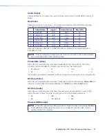
a crossover cable (see figure 4 for RJ-45 wiring instructions).
1 2 3 4 5 6 7 8
RJ-45
Connector
Insert Twisted
Pair Wires
Pins:
A cable that is wired as TIA/EIA T568A at one
end and T568B at the other (Tx and Rx pairs
reversed) is a "crossover" cable.
A cable wired the same at both ends is called
a "straight-through" cable because no pin/pair
assignments are swapped.
T568B
T568A
T568B
T568B
Straight-through Cable
(for connection to a switch, hub, or router)
End 1
End 2
Pin
Wire Color
Pin Wire Color
1
white-orange
1
white-orange
2
orange
2
orange
3
white-green
3
white-green
4
blue
4
blue
5
white-blue
5
white-blue
6
green
6
green
7
white-brown
7
white-brown
8
brown
8
brown
Crossover Cable
(for direct connection to a PC)
End 1
End 2
Pin
Wire Color
Pin Wire Color
1
white-orange
1
white-green
2
orange
2
green
3
white-green
3
white-orange
4
blue
4
blue
5
white-blue
5
white-blue
6
green
6
orange
7
white-brown
7
white-brown
8
brown
8
brown
Figure 4.
RJ-45 Wiring Instructions
figure 4
Ground
Receiv
e
Tr
ansmit
Tx Rx
RS-232
G
REMOTE


