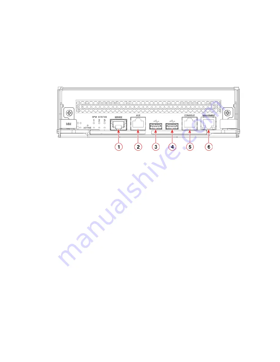
2. Connect the RJ-45 serial cable provided with the device to the console port on the active management module.
NOTE
The active management module has the LED labeled ACTIVE on the front panel illuminated in blue.
Use the port labeled CONSOLE, as shown in the following figure.
FIGURE 30
Management module front panel
1.
Service Ethernet port, 10G/1G/100M
2.
Auxiliary console port
3.
USB port
4.
USB port
5.
Console port
6.
Management Ethernet port, 1G/100M/10M
NOTE
The console or serial port is intended primarily for the initial setting of the IP address.
3. Access the device using a terminal emulator application (such as HyperTerminal in a Windows environment or Tip in a UNIX
environment).
4. Disable any serial communication programs running on the workstation (such as synchronization programs).
Establishing a serial connection
ExtremeRouting SLX 9850-4 Hardware Installation Guide
64
9035474-02 Rev AA
Содержание ExtremeRouting SLX 9850-4
Страница 10: ...ExtremeRouting SLX 9850 4 Hardware Installation Guide 10 9035474 02 Rev AA...
Страница 22: ...ExtremeRouting SLX 9850 4 Hardware Installation Guide 22 9035474 02 Rev AA...
Страница 30: ...ExtremeRouting SLX 9850 4 Hardware Installation Guide 30 9035474 02 Rev AA...
Страница 56: ...ExtremeRouting SLX 9850 4 Hardware Installation Guide 56 9035474 02 Rev AA...
Страница 94: ...ExtremeRouting SLX 9850 4 Hardware Installation Guide 94 9035474 02 Rev AA...
Страница 102: ...ExtremeRouting SLX 9850 4 Hardware Installation Guide 102 9035474 02 Rev AA...
Страница 114: ...ExtremeRouting SLX 9850 4 Hardware Installation Guide 114 9035474 02 Rev AA...
Страница 118: ...ExtremeRouting SLX 9850 4 Hardware Installation Guide 118 9035474 02 Rev AA...
Страница 136: ...ExtremeRouting SLX 9850 4 Hardware Installation Guide 136 9035474 02 Rev AA...
Страница 146: ...ExtremeRouting SLX 9850 4 Hardware Installation Guide 146 9035474 02 Rev AA...
Страница 150: ...ExtremeRouting SLX 9850 4 Hardware Installation Guide 150 9035474 02 Rev AA...


