background image

11                                     96VTR      Ver. 2.0   11/99
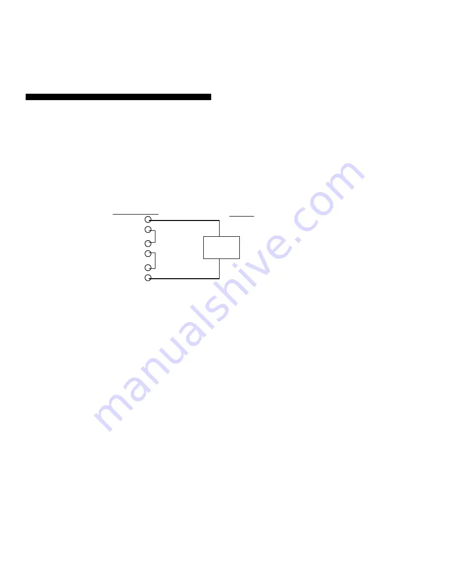
 

Control
Relay

Alarm
Relay

AC

Load

Example of Wiring Alarm and Control Relays in Series

Meter Contacts

Figure 4

16

18

12

13

19

20

 
The controller's output percent will now appear on the SV display preceded by an 'H" 
for Heating or a 'C' for Cooling (depending upon how the action of the controller is 
configured under the parameter 'act'). The 'MA' Manual status LED will also illuminate 
and flash. To manually adjust the controller's output, use the UP and DOWN arrow 
keys. For controllers using two control outputs (primary and secondary), the SV display 
will automatically toggle between outputs 1 and 2. To return to normal operation, press 
and hold the RETURN key until the 'MA' LED extinguishes. To Lock this feature, press 
and hold the UP and RETURN keys until the display flashes. While locked, the Manual 
Mode is inaccessible. 


11. RAMP-TO-SETPOINT AND EVENT/SOAK TIMER FUNCTIONS 

The Extech 96VTR controller operates as a fixed setpoint controller. However, the 
controller offers several advanced features which can enhance your application. These 
include Ramp-to-Setpoint and Event/Soak Alarm/Timers. 
 

11.1 Ramp-to-Setpoint ('rAmP' Parameter)


To limit the rate at which the controller allows the process (PV) to move towards 
setpoint (SV), enter a limit value in degrees (or other units) per minute in the 'rAmP' 
parameter. The programmable limit ranges from 0.0 to 100.0 units per minute. The 
controller will automatically adjust the controller's outputs to maintain the desired limit 
programmed by the user. A setting of zero defeats the Ramp-to-Setpoint function. 

 
11.2 Soak Timer Function (for use with Alarm 1 only) 

The Alarm 1 Soak Timer allows the process to ramp to a setpoint and remain (Soak) at 
that setpoint for a user-programmable period of time.  Set the "A1Fu" parameter to 
either '10' (Soak ON-TIMER) or '11' (Soak OFF-TIMER) depending upon the 
application (See 
Appendix A, Table 
IV, for the 
difference between 
ON- and OFF-
TIMERS). Set the 
Soak time in 
parameter 'timE' in 
the First 
Programming Level. 
The Output and 
Alarm Relays must 
be wired in series 
so that the Alarm 
relay can switch the control relay at the appropriate times (refer to Fig. 4).  For 
example, when a setpoint of 500

o

F is reached, the Soak time (programmed by the user 

under parameter 'timE") begins to countdown. After the desired Soak time has elapsed, 
the Alarm relay switches thereby switching the Control relay. 


11.3 Event Timer (Alarm 1 relay only) 

Alarm relay 1 can be programmed to switch state at desired times in a process. This is 
accomplished by first setting the alarm function in parameter "A1Fu" to either an 
EVENT-ON or EVENT-OFF Timer (See Appendix A, Table IV, for the difference 
between ON- and OFF-TIMERS). Next, pick a count-down time. The relay timer will 
start counting down once the PV equals the SV. The duration of the count-down is set 
by the user at parameter "timE". 
 
Application example: While maintaining a certain temperature for 4 hours, an event is 
to take place 2 hours into the process. The event, in this example, is the controller's 
alarm relay activating a pump. To do this, set the alarm function to an EVENT-ON 

Содержание 96VTR

Страница 1: ...red setpoint This Three Mode PID controller offers Simultaneous Process Value PV and Setpoint Value SV display Automatic alarm functions 11 in all Autotuning automatically tailors the controller s res...

Страница 2: ...emperature 4 to 140 o F 20 to 60 o C Dimensions Cutout 3 58 x 3 58 0 02 91 0 x 91 0mm 0 5mm 2 2 Input Specifications Thermocouple inputs Programmable Types J K T E B R S N Cold Junction Compensation T...

Страница 3: ...Manual Reset 0 to 100 of Prop Band Hysteresis 0 0 to 25 5 of Full Scale 3 MOUNTING AND WIRING 3 1 Prepare a 3 58 x 3 58 0 02 91 0 x 91 0mm 0 5mm panel cutout refer to Fig 2 The panel on which the cont...

Страница 4: ...which the controller s output s will adjust the process To change the setpoint use the up down arrow keys The setting range equals the range the user selects in the LoLt Low Limit and HiLt High Limit...

Страница 5: ...ow each parameter title as you scroll through the list Also to activate an autotuning session press and hold this key for 5 seconds UP Arrow Key Increases the Setpoint SV and increments parameter data...

Страница 6: ...Then program the desired limit here Allowable setting range is limited by parameter LoLt and HiLt Low and High Limit settings 7 SECOND PROGRAMMING LEVEL PARAMETERS Press and hold the SCROLL and RETUR...

Страница 7: ...cked 14 same as 2 but levels 2 3 4 locked 9 same as 1 w levels 3 4 locked 15 same as 3 but levels 2 3 4 locked A1Fu Alarm 1 Function Select an Alarm Timer function from the function list in Appendix A...

Страница 8: ...OFF OFF ON ON 11 ON OFF ON ON 4 OFF ON OFF OFF 12 ON ON OFF OFF 5 OFF ON OFF ON 13 ON ON OFF ON 6 OFF ON ON OFF 14 ON ON ON OFF 7 OFF ON ON ON 15 ON ON ON ON Addr Controller address used with the RS...

Страница 9: ...alue which will display when a 4mA signal is applied to the controller For example for a 4 20mA unit to display from 50 to 150 set LoCA to 50 e Press and hold the RETURN key for at least 5 seconds and...

Страница 10: ...will extinguish The new Tuning values will now be stored in nonvolatile memory Adjustments can be made manually if desired in programming level 2 e To abort an Auto Tune process simply press and hold...

Страница 11: ...s outputs to maintain the desired limit programmed by the user A setting of zero defeats the Ramp to Setpoint function 11 2 Soak Timer Function for use with Alarm 1 only The Alarm 1 Soak Timer allows...

Страница 12: ...nce and proper packaging to prevent damage in transit This warranty does not apply to defects resulting from action of the user such as misuse improper wiring operation outside of specification improp...

Страница 13: ...e Same as the Process Low Alarm but no relay action takes place until the process PV reaches the setpoint for a second time Standby sequence is also known as Startup Inhibit and is useful for avoiding...

Страница 14: ...nding upon the alarm type where no relay action can occur to eliminate relay chatter Act Action This is control output action Set to 1 for heating unit Set to 1 for o F dp decimal point Set to 0 for n...

Страница 15: ...which the controller s secondary cooling output is permitted to throttle between 0 and 100 Outside this region the controller s secondary output is either 0 above the band or 100 below the band Figure...

Отзывы: