background image

Ver: IC13-EN-10567

Operating and Maintenance Manual

19 June 2007

I-C13 Impactor

Operating and Maintenance Manual

Manufactured by:

Extec Screens & Crushers Ltd

Address:

Hearthcote Road

Swadlincote

Derbyshire

DE11 9DU

United Kingdom

Telephone:

+44 (0)1283 212121

Fax:

+44 (0)1283 226465

Parts and Service:

+44 (0)8000 181945

www:

http://www.extecscreens.com

Содержание I-C13 Impactor

Страница 1: ...Impactor Operating and Maintenance Manual Manufactured by Extec Screens Crushers Ltd Address Hearthcote Road Swadlincote Derbyshire DE11 9DU United Kingdom Telephone 44 0 1283 212121 Fax 44 0 1283 22...

Страница 2: ...anufacturer in regard to this machine Whilst every effort has been made to ensure the accuracy of information contained within this manual Extec Screens Crushers Ltd can assume no responsibility for a...

Страница 3: ...onformity Page iii I C13 Impactor Certificate of Conformity Supply of Machinery Safety Regulations Machinery Directive 98 37 EC Serial No Engine Serial No Production Manager Date of build Issued Decla...

Страница 4: ...uding number title issue date and other relative documents EN292 1 EN292 2 EN349 EN418 EN954 1 EN1050 Place of issue Extec Screens Crushers Ltd Originating certification by Laidler Associates Belasis...

Страница 5: ...Protective Equipment PPE 7 1 8 Measured Noise Level 8 1 9 Vibration Levels 8 1 10 Organisational Safety Measures 8 1 11 Personnel Qualification Requirements and Responsibilities 9 1 12 Safety Advice...

Страница 6: ...Description 19 3 4 Key Features of the I C13 Impactor 20 3 5 Common Applications 20 3 6 Machine Layout Indicating Main Components 21 3 7 Emergency Stop Positions 22 3 8 Data 22 Crusher 22 Feeder 22 Co...

Страница 7: ...sing Bearings 55 5 3 4 Inspecting Adjusting Belt Sealing Rubbers 56 5 3 5 Adjusting Belt Scraper 56 5 3 6 Hydraulic Filter 57 5 3 7 Changing Hydraulic Water Trap 58 5 4 250 Hour Maintenance Schedule 5...

Страница 8: ...159 Recirculation Vibrating Grid 161 Recirculation Fines Conveyor 165 Recirculation Side Conveyor 170 Stickers English 174 Transport Bogie and Fifth Wheel Optional 180 Water Pump Optional 183 Appendix...

Страница 9: ...g C 26 11 2003 Shell Naturelle Fluid HF M 46 ACKXR GB eng C 09 06 2004 Shell Tellus Oil 46 ACKQ6 GB eng C 29 04 2004 Shell Omala 220 Gear Oil ACH75 GB eng C 29 01 2003 Shell Safe Anti Freeze L84042 Re...

Страница 10: ...Page x Contents Ver IC13 EN 10567 I C13 Impactor...

Страница 11: ...rrying out any maintenance adjustment or removing any guards or covers e Always follow the procedures outlined in the operating and maintenance instruction f If in doubt ask Do not take personal risk...

Страница 12: ...g stickers Observe all safety instructions and warnings attached to the plant Ensure that safety instructions and warnings attached to the plant are always complete and perfectly legible Keep warning...

Страница 13: ...Ver IC13 EN 10567 Safety Instructions Page 3 I C13 Impactor...

Страница 14: ...Page 4 Safety Instructions Ver IC13 EN 10567 I C13 Impactor...

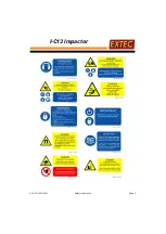
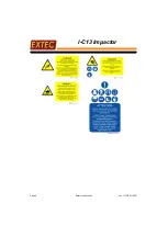
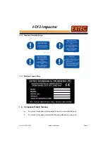
Страница 15: ...I C13 Impactor 1 3 2 Machine Safety Warnings 1 3 3 Machine Legend Plate 1 4 Component Safety Features a Do not use this equipment with guards removed or incorrectly fastened b Do not use this equipmen...

Страница 16: ...e f If for any reason other areas need to be accessed the risk associated with the activity must be assessed and appropriate control measures implemented 1 6 Environmental Safety It is essential that...

Страница 17: ...topped If this is not practical remember to keep tools test equipment and all other parts of your body well away from the moving parts c For reasons of safety long hair must be tied back or otherwise...

Страница 18: ...d local conditions will affect the noise levels Ear protection is compulsory within 10 meters of the machine when the engine and all other parts of the machine are running 1 9 Vibration Levels There a...

Страница 19: ...Any work on and or with the plant must be executed by trained reliable and authorised personnel only Statutory minimum age limits must be observed b Work on electrical system and equipment of the pla...

Страница 20: ...ance and intervals set out in these operating instructions except where a Warning horn light gauge or indicator calls for immediate action b Adverse conditions necessitate more frequent servicing c Al...

Страница 21: ...ng Falling Falling from and or onto this plant could cause injury or even death Never climb on the plant whilst it is in operation Never use plant parts as a climbing aid Always keep the area around t...

Страница 22: ...ydraulic fluid lines for leaks loose connections chafe marks and damage Any defects found must be rectified without delay 1 13 7 Removal of Safety Devices and Guards All safety devices control devices...

Страница 23: ...e plant Report the incident and have the live wire de energized Machine Electrical Work on the electrical system or equipment may only be carried out by a skilled and qualified electrician or by speci...

Страница 24: ...air Dust waste must only be handled by authorised persons dampened placed in a sealed container and marked to ensure safe disposal 1 14 3 Welding or Naked Flames Welding flame cutting and grinding wo...

Страница 25: ...practice extreme cleanliness when servicing hydraulic components Hydraulic fluid under pressure can penetrate the skin causing serious injury If fluid is injected under the skin it must be surgically...

Страница 26: ...Page 16 Safety Instructions Ver IC13 EN 10567 I C13 Impactor Intentionally left blank...

Страница 27: ...ck of a tractor The bogie fits at the front of the machine underneath the main conveyor This is installed by lowering all four jack legs to lift the machine off the ground allowing the bogie to be rol...

Страница 28: ...urements of the machine should be checked to ensure they are within the legal transport dimensions Figure 2 1 I C13 Impactor Transport Dimensions Figure 2 2 I C13 Impactor Transport Dimensions Includi...

Страница 29: ...er working parts of the machine are hydraulically driven Where possible all of the moving parts of this machine are guarded where not warnings are provided The Safety Section of this manual must be re...

Страница 30: ...tomatically coordinates the flow of material from the vibrating feeder to the impactor Speed of the impactor can be varied between 500 765 rpm thereby varying the product size Unique fast track system...

Страница 31: ...ease contact Extec Screens Crushers Ltd for further details of performance figures and advice on your material 3 6 Machine Layout Indicating Main Components Figure 3 1 Main Components HYDRAULIC CONTRO...

Страница 32: ...rgency Stop Positions 3 8 Data Crusher Feed Opening 1290 x 950 mm Crusher Speed 500 765 rpm Drive Hydraulic Feeder Hopper Width 2751 mm Feeder Width 1100 mm Feeder Length 4000 mm Hopper Capacity 5 3 c...

Страница 33: ...idth 2756 mm Transport Height 3911 mm Working Length 14017 mm Working Width 4107 mm Working Height 4023 mm Weight 44 000 kg Engine Details Engine Caterpillar C 13 Industrial C 440 bhp Engine Maximum P...

Страница 34: ......

Страница 35: ...rds are in place with all safety devices operating correctly Never start this equipment without guards and safety devices operating correctly 6 Ensure that crusher chamber feeder and conveyor belts ar...

Страница 36: ...ol 5 Diagnostic Lamp 6 Warning Lamp 7 Engine rpm Meter 8 Interlock ON OFF 9 Main Conveyor ON OFF 10 Side Conveyor ON OFF 11 Magnet ON OFF 12 Crusher ON OFF 13 Feeder ON OFF 14 Feeder Pan ON OFF 15 Tra...

Страница 37: ...a safety shutdown and turn the engine off If a safety shutdown occurs the condition causing the engine to shut down must be corrected before any attempt is made to restart it Start Feeder Stop Feeder...

Страница 38: ...ing this time When this is done stop all systems turn engine speed switch to No 2 and restart all systems DO NOT turn engine speed switch from position 1 to 2 while any systems are running DO NOT oper...

Страница 39: ...D ALONG EACH SIDE OF THE MACHINE OR BY TURNING THE IGNITION KEY OR ISOLATION SWITCH DIRECTLY TO OFF POSITION ENSURE THAT ALL PERSONNEL IN THE VICINITY OF THE MACHINE ARE FULLY AWARE OF THE LOCATION OF...

Страница 40: ...wer the jacking legs ALL of the leg transportation retaining screws MUST be removed 1 Remove jacking leg retention screws 2 Front jacking legs lever 3 Lower front jacking legs to raise fifth wheel nec...

Страница 41: ...er rear jacking legs to raise machine clear of the bogie locking mechanism 8 Remove bogie air brakes lighting connections then tow away from machine 9 Retract both front and rear jacking legs so that...

Страница 42: ...back door being raised 13 Raise hopper back door 14 Hopper back door being raised 15 Hopper sides fully raised 16 Remove connection panel umbilical cord completely from machine IMPORTANT Before trans...

Страница 43: ...is equipment must never be tracked on gradients that are more than 10 degrees Port to Starboard or 20 degrees Front to Back The machine must always be on flat solid ground when operating in its normal...

Страница 44: ...ound suitable for carrying the weight of the machine Prior to operating the machine it is ESSENTIAL that both tracks are in contact with firm level ground to avoid excessive vibration or rocking of th...

Страница 45: ...r for Operation 1 Press button Interlock On 2 Remove side conveyor locking pin 3 Activate lever marked side con fold to lower side conveyor 4 Side conveyor in working position 5 Raise main conveyor sp...

Страница 46: ...during transport 2 Unfold ladder ensuring its locked into position 3 Lift rail into position and lock with pin 4 Lift up rotating gate section Note While operator is using the platforms the safety ga...

Страница 47: ...it Where fitted The recirculation unit is provided separately 6 Lower rear jack legs by operating levers 7 Lower front jack legs by operating levers 8 Fit pins R clips to jack legs 8 off Where a recir...

Страница 48: ...ents DO NOT stand on any part of the engine whilst operating or carrying out any installation on the machine All adjustments must ONLY be carried out by trained personnel All adjustments to modify hyd...

Страница 49: ...Ver IC13 EN 10567 Commissioning and Operation Page 39 I C13 Impactor 3 Remove the lock pins 4 Extend the support and install the pin...

Страница 50: ...EN 10567 I C13 Impactor 5 Install the main conveyor in position on the crusher 6 Use the lever to lower the hydraulic arms 7 Install the hydraulic arms on the supports 8 Attach the spacer bush and th...

Страница 51: ...otor 11 Install the hydraulic hoses from their match marks 12 Install the support bracket box and attach the support bracket 13 Put the recirculation conveyor in position and attach the lower end to t...

Страница 52: ...r IC13 EN 10567 I C13 Impactor To attach the recirculation conveyor perpendicular to the impactor do the steps that follow 16 Install the screen mesh 17 Tighten the screen mesh with the handle 18 Put...

Страница 53: ...the Impactor is started Starting Procedure on page 28 19 Attachment points of the chassis 20 Attachment points of the recirculation conveyor 21 Attach the two support cables to the impactor chassis an...

Страница 54: ...eady to be operated To operate machine turn engine speed to No 2 position and then start systems in the following sequence 1 Side conveyor 2 Magnet 3 Main conveyor 4 Feeder pan 5 Impactor 6 Feeder 3 U...

Страница 55: ...pment DO NOT use excavators to force any material into feeder as any damage occurred from this action will invalidate any Extec Screens Crushers Ltd warrantees 3 Material should be fed carefully not d...

Страница 56: ...crusher becoming choked with material as the machine will have more time to deal with what is in the crusher chamber Once the pressure in the crusher chamber drops to within specified limits the feede...

Страница 57: ...crusher on speed on No 2 then stop impactor The pressure gauge should read 250 bar If required adjust the pressure using following procedure 3 Unscrew lock nut on relief valve grub screw To reduce th...

Страница 58: ...ing procedure 3 Unscrew lock nut on relief valve grub screw To reduce the pressure turn the screw anti clockwise To increase pressure turn the screw clockwise Turn screw about of a turn 4 Repeat proce...

Страница 59: ...isolated with the ignition keys removed BEFORE making any adjustments DO NOT stand on any part of the engine whilst operating or carrying out any maintenance on the machine All adjustments must ONLY b...

Страница 60: ...l pump and fuel suction pipe Alternatively refill manually after cleaning around the cap opening 5 Bleed diesel water trap 6 Check radiator water level refill if necessary Use a 50 50 mixture of anti...

Страница 61: ...aner Note Service indicators are for showing when the air filter needs to be replaced or cleaned Test the service indicator as laid out in the engine manufacturer s handbook 1 Check the service indica...

Страница 62: ...ut any maintenance on the machine All adjustments must ONLY be carried out by trained personnel 5 Cover the turbocharger air inlet in order to keep dirt out Clean the inside of the air cleaner cover a...

Страница 63: ...sed air 5 Check blow bars for wear and turn around or replace if necessary 6 Check condition of service indicators on hydraulic filters water trap and air breather Replace if necessary 7 Examine liner...

Страница 64: ...Level 1 Remove oil level plug If oil trickles out there is enough oil in feeder if not oil level needs to be topped up 2 Remove oil filler plug Refill using Shell Omala 220 Gear Oil until oil comes ou...

Страница 65: ...se where otherwise indicated Using suitable equipment the following bearings must be greased every week See following pictograms for details of grease points If the service indicator is green it is ti...

Страница 66: ...amp fixing screws If required adjust head drum scraper by loosening bolts in Rosta springs adjusting scraper and re tightening bolts Both sides should be adjusted simultaneously Figure 5 2 Adjusting B...

Страница 67: ...TER INDICATORS IS THE ONLY CHECK TO BE MADE WHEN MACHINE IS RUNNING STOP MACHINE BEFORE REPLACING ELEMENTS 1 Lift up cover inspect service indicator 2 Replace elements if service indicator is red Note...

Страница 68: ...hrough the crusher and off the conveyor belts b Stop the machine and replace the hydraulic filters with 3 micron flushing filters EN1405 c Fit new 10 micron water trap d Check condition of hydraulic t...

Страница 69: ...ange oil in vibrating feeder 3 Change diesel filters 4 Change oil in tracks 5 5 1 Changing Oil in Tracks To drain oil from the track gearbox drive the machine until the oil drain plug is at the bottom...

Страница 70: ...l oil has been replaced in tracks Remove the oil level plug as shown in the photographs below Fill with oil into the oil level plug until it starts to come out of the plug hole Replace oil level plug...

Страница 71: ...ack adjuster grease valve D 5 6 2 Track Adjustment Settings In order to establish if the track requires tensioning move the Host machine a few metres forwards and backwards on level ground This allows...

Страница 72: ...ion cover on the side of the track frame as shown at F 2 Ensure that the track adjuster valve H is tight 3 Attach the special grease gun connector G to a grease gun and fit it onto the track adjuster...

Страница 73: ...the track frame as shown at F 2 Loosen the track adjuster valve H by turning it one half turn anticlockwise 3 Grease should now escape slowly from the track tensioning cylinder and the track should sl...

Страница 74: ...rease Points Temperature Viscosity Manufacturers Equivalent Specifications Anti Freeze Shell Safe Anti Freeze Concentrate Diesel Shell Agricultural Gas Oil Engine Oil Shell Diesel Engine Oil Rimula Ul...

Страница 75: ...re battery and over speed warning lights on electrical control panel Crusher won t start Check that Crusher button is ON in electrical box Check fuel level Check hydraulic oil level in tank Check that...

Страница 76: ...crusher operates If Crusher operates and levers are central but the machine still won t track this may indicate an electrical problem Contact Extec Screens Crushers Ltd immediately Main Side or Magne...

Страница 77: ...rt 100 bar this should drop to 50 bar when warm Peak pressure 200 bar 3 Feeder pan 50 bar Peak pressure 200 bar 4 Main conveyor 50 bar Peak pressure 240 bar 5 Magnet 30 bar Peak pressure 200 bar 3 Che...

Страница 78: ...e jaw remote switch Case 1 Receiver believes it is receiving a signal from a handset Lamp state as follows Lamp above jaw remote switch Flashing Lamp above interlock off switch Lit Lamp above interloc...

Страница 79: ...re in the crimp contacts Check yellow and white wires inside switch box are securely fitted to screw terminals Check yellow and white wires from screw terminal inside switch box to 36 way connector on...

Страница 80: ...Page 70 Trouble Shooting Guide Ver IC13 EN 10567 I C13 Impactor Intentionally left blank...
Страница 81: ...ctor Appendix A Parts Manual Contact Details Extec Screens Crushers Ltd Hearthcote Road Swadlincote Derbyshire DE11 9DU United Kingdom Telephone 44 0 1283 212121 Fax 44 0 1283 226465 Parts and Service...

Страница 82: ...ime of publication However with Extec Screens Crushers Ltds policy of continually improving their products your machine may not coincide exactly with this manual Therefore before placing any order for...

Страница 83: ...105 Crusher Box 108 Torque Arm Assembly 113 Main Conveyor 115 Extended Main Conveyor Where fitted 121 Side Conveyor 130 Feeder Pan 135 Hydraulic Hoses 142 Recirculation Layout Where fitted 150 Recirc...

Страница 84: ...Part No Part Description Quantity 1 EL2069 MANUAL HANDSET 1 2 EL2009 UMBILICAL CHORD 7 m 1 3 EL2104 REMOTE CONTROL HANDSET CHARGER UK ONLY 1 4 EL2105 REMOTE CONTROL HANDSET CHARGER CONTINENT ONLY 1 5...

Страница 85: ...REMOTE CONTROL 1 8 EL4418 REMOTE CONTROL HANDSET 433 MHz 1 9 EN4420 FEEDER REMOTE CONTROL 1 10 HAH101401 FUEL SUCTION PIPE 1 11 IM1036 LIFTING GEAR 1 12 PN1088 JACKING LEG SUPPORT PINS 8 13 J2910000...

Страница 86: ...Page 76 Chassis Walkways and Tracks Ver IC13 EN 10567 I C13 Impactor AA 2 Chassis Walkways and Tracks 1 CHASSIS ASSEMBLY 2 CHASSIS FRONT END 3 CHASSIS REAR END 19 35 18 11 28 10 26 9 13 12...

Страница 87: ...Ver IC13 EN 10567 Chassis Walkways and Tracks Page 77 I C13 Impactor 4 JACKING LEG 5 JACKING LEG MOUNTED 6 WALKWAY 15 43 41 39 1 40 44 17 30 31 21 22 23 16 27 29 36 37 34 38 20...

Страница 88: ...Page 78 Chassis Walkways and Tracks Ver IC13 EN 10567 I C13 Impactor 7 PULLEY GUARD 8 PULLEY GUARDS REAR 33 6 32 7 8 5 3 4...

Страница 89: ...INNER GUARD 1 4 A6620600 BRACKET 1 5 A6620700 BRACKET 1 6 A6630000 IMPACTOR PULLEY OUTER GUARD 1 7 A6640000 IMPACTOR PULLEY SPLIT COVER TOP 1 8 A6660000 IMPACTOR PULLEY GUARD 1 9 A8880000 MAGNET SUPPO...

Страница 90: ...H 1 26 A14960000 CONVEYOR SUPPORT BEAM 1 27 A14970000 WALKWAY BRACKET 2 28 A14990000 CROSS BRACE 1 29 A15000000 ALUMINIUM LADDER 2 30 A15240000 EMERGENCY STOP GUARD 1 31 A15250000 EMERGENCY STOP GUAR...

Страница 91: ...IRCULATION MACHINE A R 4 FAB1009 3 4 UNC X 3 BOLT 8 8 72 5 FAB16X45 M16 X 45 BOLT 6 6 FAB20X60 10 9 M20 X 60 BOLT GRADE 10 9 48 7 FAB20X80 10 9 M20 X 80 BOLT GRADE 10 9 48 8 FAS16X40 M16 X 40 SETSCREW...

Страница 92: ...TRACK CHAIN GUIDE DTL 2 18 UC2020 TRACK COMPLETE 1 19 UC3950 PC395 TRACK ROLLERS C12 18 PER PAIR 18 20 UC5002 TRACK MOTOR 2 21 UC7113 713A2FE90 GEARBOX MOTORCOMP WITH MOTION CONTROL V V 2 22 UC7120 FT...

Страница 93: ...Ver IC13 EN 10567 Hopper Page 83 I C13 Impactor AA 4 Hopper 1 HOPPER DOORS 2 HOPPER RAMS 21 7 22 11 9 10 8 19 16 18 17 15 5 6 12 13 14 20...

Страница 94: ...1 10 C9260000 HOPPER L H SIDE DOOR 1 11 C9270000 HOPPER REAR DOOR 1 12 C9280000 HOPPER FRONT SIDE LINER PLATE 10mm M S 2 13 C9290000 HOPPER REAR SIDE LINER PLATE 10mm M S 2 14 C9300000 HOPPER REAR DO...

Страница 95: ...T SUPPORT FRAME DRIVE SIDE 1 2 A8890000 MAGNET SUPPORT FRAME 1 3 FAEB1002 M24 LIFTING EYE 4 4 HM1010 BELT DRIVE MOTOR 305 cc 1 5 MA1001 COUPLEX CONNECTOR 4 6 MA1050 CP20 80SC2 ERIEZ MAGNET 1 7 MA1051...

Страница 96: ...r Pack Ver IC13 EN 10567 I C13 Impactor AA 6 Power Pack 1 R H VIEW OF POWER PACK 2 L H VIEW OF POWER PACK 7 9 12 23 15 19 14 22 25 21 8 58 55 55 52 Hidden 1 2 Hidden 16 50 51 29 11 33 19 14 30 Hidden...

Страница 97: ...Ver IC13 EN 10567 Power Pack Page 87 I C13 Impactor 3 VIEW ON BOTTOM OF POWER PACK 4 HYDRAULIC TANK 13 34 10 4 3 5 40 45 46 82 20 81 Hidden 44 98 41...

Страница 98: ...Page 88 Power Pack Ver IC13 EN 10567 I C13 Impactor 5 HYDRAULIC TANK BELOW RETURN FILTERS 6 97 59 65 68 67 66 84 49 86 85 83 103 26 90 63 62 99 101 47...

Страница 99: ...Ver IC13 EN 10567 Power Pack Page 89 I C13 Impactor 7 VIEW ON AIR FILTER 8 VIEW ON VALVE PLATE ASSEMBLY 17 18 48 37 38 16 36 27 89 88 93 95 87...

Страница 100: ...Ver IC13 EN 10567 I C13 Impactor 9 VIEW ON SOLENOID VALVE 10 VIEW ON 5 STATION MANIFOLD BLOCK 11 HYDRAULIC WATER TRAP 12 VIEW ON TOP OF POWER PACK 13 VIEW INSIDE POWER PACK 92 91 99 88 95 94 89 6 39...

Страница 101: ...PLATE Part No Part Description Quantity 1 A4870000 PACKER A R 2 A16510000 PIPE TRAY 1 3 B1300000 HYDRAULIC TANK LID 1 4 B1310000 HYDRAULIC TANK LID 1 5 B2410000 HYDRAULIC TANK LID GASKET 2 6 B3260000...

Страница 102: ...1 23 B6990000 OIL COOLER BRACKET 1 24 B7320000 SIDE INFILL PANEL NO OIL COOLER A R 25 B7330000 OIL COOLER MESH 1 26 B7340000 C13 POWER PACK SUCTION PIPE 1 27 B7570000 VALVE PLATE ASSEMBLY 1 28 B77400...

Страница 103: ...550 NM GAS STRUT 2 55 FD2007 MOULDED PLASTIC HANDLE 5 56 FD2102 HINGE 2 57 FD2105 HINGE 3 2 HOLE 2 58 FD3114 ANTI LOOSE FASTENER 2 59 HA01200018 M M ADAPTOR 1 60 HA03400007 x 1 M M 1 61 HA03400044 M M...

Страница 104: ...ENGINE 1 86 HP1058 PTO PUMP 1 87 HV1056 HC D40 CONTROL VALVE 2 88 HV3017 4 STATION CETOP 3 SERIES INCL HV3521 HV3522 HV8501 1 89 HV3021 FRFEXT 2381 24 5STATION SOLENOID BLOCK INCL HV3527 HV3528 1 90 H...

Страница 105: ...Ver IC13 EN 10567 Control Boxes Page 95 I C13 Impactor AA 7 Control Boxes 1 ELECTRICAL CONTROL BOX 2 HYDRAULIC CONTROL BOX 7 5 26 10 6 27 26 25 9 27 30 28...

Страница 106: ...Control Boxes Ver IC13 EN 10567 I C13 Impactor 3 RECIRCULATION CONTROL BOX WHERE FITTED 4 VIEW ON ISOLATION SWITCH AND BATTERIES 5 VIEW ON WATER MANIFOLD 14 12 13 11 Hidden 21 19 18 24 8 16 17 22 23 2...

Страница 107: ...30000 EMERGENCY STOP GUARD 2 8 A14390000 BATTERY LOCATION ANGLE 1 9 A14730000 HYDRAULIC CONTROL BOX 1 10 A14740000 ELECTRICAL CONTROL BOX 1 11 A16210000 ISOLATOR ACCESS COVER 1 12 A16220000 RE CIRC HY...

Страница 108: ...24 EL3010 BATTERY CROSSOVER 1 25 FD1007 GAS STRUT ONE EYE 4 26 FD2006 CHROME PULL HANDLE 6 27 FD2109 POLIALL HINGE 2 28 HV1020 4 LEVER SPOOL VALVE 1 29 HV1049 6 LEVER SPOOL VALVE 1 30 HV2002 FLOW DIV...

Страница 109: ...Description Quantity 1 A10800000 DIESEL PUMP GUARD 1 2 A12500000 DIESEL TANK 1 3 A12510000 DIESEL TANK LID 1 4 A12530000 DIESEL TANK STRAPS 2 5 A14040000 DIESEL TANK PLATFORM 1 6 EN1609 FILLER CAP 1 7...

Страница 110: ...eder and Vibrator Box Ver IC13 EN 10567 I C13 Impactor AA 9 Feeder and Vibrator Box 1 FEEDER ASSEMBLY VIEW ON TOP FROM MOTOR SIDE 2 FEEDER ASSEMBLY VIEW FROM BOTTOM FROM GEAR SIDE 41 39 2 40 1 36 4 5...

Страница 111: ...01 I C13 Impactor 3 VIEW ON BOTTOM FROM MOTOR SIDE 4 VIEW ON MOTOR AND COVERS 5 GEAR SIDE WITHOUT GEARS FITTED 6 VIEW ON BEARING CARTRIDGE 7 GEAR SIDE GEARS FITTED 8 VIEW ON GEAR SIDE WITH COVER 12 11...

Страница 112: ...67 I C13 Impactor 9 VIBRATOR BOX INSIDE 10 VIBRATOR BOX MOTOR SIDE 11 VIBRATOR BOX MOTOR SIDE 12 VIBRATOR BOX MOTOR SIDE 13 VIBRATOR MOTOR ASSEMBLY 14 VIEW ON FEEEDER SUPPORT SPRINGS 22 14 34 23 17 26...

Страница 113: ...OVER PLATE 1 12 H2030000 GASKET INSPECTION COV ER PLATE 1 13 H2080000 GEAR END COVER NON DRIVE 1 14 H2090000 VIBRATOR BEARING CARTRIDGE 4 15 H2100000 BEARING RETAINING PLATE NON DRIVE 2 16 H2140000 SP...

Страница 114: ...TLET CHUTE FRONT SECTION 1 36 H2750000 WEAR PLATE R H S 1 37 BT6514 SPIDER 1 38 BT5020 TAPER LOCK BUSH 1 39 H2310000 FEEDER WEAR PLATE 2 40 H2730000 OUTLET WEAR PLATE 1 41 H2740000 WEAR PLATE L H S 1...

Страница 115: ...Ver IC13 EN 10567 Transfer Chute Page 105 I C13 Impactor AA 10 Transfer Chute 1 TRANSFER CHUTE ASSEMBLY 2 VIEW ON DISCHARGE END 5 4 9 8 1 6 16 7 2 12 15 3...

Страница 116: ...Page 106 Transfer Chute Ver IC13 EN 10567 I C13 Impactor 3 OPPOSITE HAND TRANSFER CHUTE ASSEMBLY 4 TRANSFER CHUTE TUBBER 10 11 14 14...

Страница 117: ...HUTE 1 5 A9850000 TRANSFER CHUTE COVER PLATE 1 6 A9860000 IMPACTOR CHUTE RUBBER CLAMP 2 7 A10160000 TRANSFER CHUTE REAR CLAMP 1 8 A13560000 TRANSFER CHUTE HANDLE 9 A14120000 MOUNTING BRACKETS 2 10 A16...

Страница 118: ...e 108 Crusher Box Ver IC13 EN 10567 I C13 Impactor AA 11 Crusher Box 5 View on Pulley Guard With Door Open 6 Detail View on Pulley Wheels 7 Detail View on Pulley Wheels 28 24 2 22 3 23 22 5 27 10 25 2...

Страница 119: ...Ver IC13 EN 10567 Crusher Box Page 109 I C13 Impactor 8 View on Torque Arm and Crusher Drive Motor 9 Inlet to Crusher Box Viewed From Feeder 7 29 1 30 26 4 13 14 12 9...

Страница 120: ...Page 110 Crusher Box Ver IC13 EN 10567 I C13 Impactor 10 HYDRAULIC CONTROL BOX 11 HYDRAULIC CONTROL BOX 20 8 8 20 8 31 20...

Страница 121: ...LEY GUARD DOOR 1 4 A6640000 DRIVE PULLEY GUARD 1 5 A6660000 DRIVEN PULLEY GUARD 1 6 CRUSHER TO FEEDER PAN OUTER RUBBER 2 7 J0930000 PIVOT ARM 1 8 J2760000 CRUSHER INLET BOTTOM RUBBER CLAMP PLATE 2 9 J...

Страница 122: ...RUBBER CLAMP PLATE 2 21 J5620000 SIDE RUBBER CLAMP SPACER 10 22 BT4035 SPC PULLEY 1 23 BT4040 SPC PULLEY 1 24 BT4506 SPC4750 PULLEY BELT 6 25 BT5017 TAPER LOCK BUSH 1 26 J6960000 TURN BUCKLE ASSEMBLY...

Страница 123: ...ion Quantity 1 A6610000 MOUNTING PIN 1 2 A13580000 BASE PLATE 1 3 BT3015 INNER BEARING 1 4 BT3016 OUTER BEARING 1 5 BT5017 TAPER LOCK BUSH 50 50 100 1 6 BT4040 400 X 10 SPC PULLEY 1 7 BT5504 LUBRICATI...

Страница 124: ...mpactor 11 J8400000 MOTOR CONTROL BLOCK 1 12 J0250000 PIN CAP 1 13 J0330000 OUTER BEARING CAP 1 14 J0820000 INNER BEARING SPACER RING 1 15 J0930000 TENSIONING FRAME 1 16 J5050000 PULLEY SHAFT 1 17 J69...

Страница 125: ...Ver IC13 EN 10567 Main Conveyor Page 115 I C13 Impactor AA 13 Main Conveyor 1 MAIN CONVEYOR TOP SECTION 2 VIEW ON FEED BOOT 29 50 34 35 59 51 28 34 35 49 43 7 16 44 60 20 61 47 30 37 38 45 46 48 1 36...

Страница 126: ...Page 116 Main Conveyor Ver IC13 EN 10567 I C13 Impactor 3 VIEW OF REAR ROLLERS 4 VIEW ON MID SECTION 8 10 11 15 14 39 36 37 42 41 13 40 33...

Страница 127: ...Ver IC13 EN 10567 Main Conveyor Page 117 I C13 Impactor 5 MAIN CONVEYOR TOP SECTION 6 VIEW ON HEAD DRUM SCRAPER 27 23 7 17 19 56 18 24 21 55 8 9 57 13 42 41 10 53 54 52 33 12 22 26 25 32 58 62 31...

Страница 128: ...CK BUSH 1 4 BT5011 2517 55 TAPER LOCK BUSH 1 5 BT6516 TX180 DRIVE COUPLING INSERT 1 6 BT6517 TX180F DRIVE COUPLING COMPLETE 1 7 CBHD160001000 CONVEYOR BELT 1 8 CR1003 MCON WING ROLLER 12 9 CR1004 30 R...

Страница 129: ...28 D5230000 HEAD DRUM FLAIR R H 1 29 D5240000 HEAD DRUM FLAIR L H 1 30 D5300000 FEED BOOT SUPPORT LEG FRONT 4 31 D5450000 TOP SCRAPER MTG PLT 1 32 D5460000 TOP SCRAPPER CLAMP PLT 1 33 D5490000 MEGABI...

Страница 130: ...99000011 ZLA2358T1 X 3 8 THREADED 2 54 HA99000012 VAA0038T1 3 8 BRASS RETAINING 2 55 HA99000013 ZPF0125D6 1 CLAMP C W VAB 2 56 HM1016 MOTOR CHARLYNN 6K490 AAA 006 1 57 PN1033 ADJUSTER BOLT M24 X 485 2...

Страница 131: ...0567 Extended Main Conveyor Where fitted Page 121 I C13 Impactor AA 14 Extended Main Conveyor Where fitted 1 EXTENDED MAIN CONVEYOR ASSEMBLY 2 VIEW ON CONVEYOR HEAD DRUM 7 49 67 62 66 64 65 63 28 18 6...

Страница 132: ...Page 122 Extended Main Conveyor Where fitted Ver IC13 EN 10567 I C13 Impactor 3 VIEW ON CONVEYOR TOP SECTION 4 VIEW ON MIDDLE SECTION 29 70 52 30 57 53 58 55 28 56 71 54 49 42 59 42 43 60 51...

Страница 133: ...Ver IC13 EN 10567 Extended Main Conveyor Where fitted Page 123 I C13 Impactor 5 VIEW ON TAIL DRUM 6 VIEW UNDERNEATH CONVEYOR 44 47 36 37 1 15 44 19 45 31 73 61 46 35 48 74 75 8 10 11 14 13 12 38...

Страница 134: ...Page 124 Extended Main Conveyor Where fitted Ver IC13 EN 10567 I C13 Impactor 7 VIEW ON DRIVE COUPLING 8 VIEW ON TOP SECTION 2 4 6 5 6 3 18 17 67 16 9 26 69...

Страница 135: ...Ver IC13 EN 10567 Extended Main Conveyor Where fitted Page 125 I C13 Impactor 9 ROSTA SCRAPER 10 FLAIR MOUNTING BRACKETS 21 76 32 72 33 Hidden 27 23 22 22...

Страница 136: ...Page 126 Extended Main Conveyor Where fitted Ver IC13 EN 10567 I C13 Impactor 11 IMPACT BLOCKS 12 41 34 40 39 68...

Страница 137: ...IMPACT ROLLER 102 x 340mm 2 14 CR1043 OUTER IMPACT ROLLER 102 x 272mm 4 15 D0100000 1000 WIDE TAIL DRUM 1 16 D0140000 HEAD DRUM 1 17 D0180000 MOTOR MTG BRACKET 1 18 D0190000 MOTOR MTG BRACKET TOP 1 19...

Страница 138: ...000 FEED BOOT CLAMP 1 47 D8410000 FEED BOOT R H SIDE GAURD 1 48 D8420000 FEED BOOT L H SIDE GAURD 1 49 D8430000 ALIMINIUM DISCHARGE CHUTE 1 50 D10150000 EXTENDED MAIN CONVEYOR TOP FRAME 1 51 D10200000...

Страница 139: ...68 HR1058 HYDRAULIC RAM 2 69 PN1033 HEAD DRUM ADJUSTER BOLT 2 70 PN1170 EXTENDED CONVEYOR LOCK OUT PIN 2 71 PN1174 EXTENDED CONVEYOR PIVOT PIN 2 72 PY1004 POLY SCRAPER 1210 X 80 X 8 1 73 RU1027 SUPER...

Страница 140: ...Page 130 Side Conveyor Ver IC13 EN 10567 I C13 Impactor AA 15 Side Conveyor 1 VIEW OF SIDE CONVEYOR 2 SIDE CONVEYOR BOTTOM SECTION 43 19 35 44 20 42 41 34 26 23 15 1 9 10 8 39...

Страница 141: ...Ver IC13 EN 10567 Side Conveyor Page 131 I C13 Impactor 3 SIDE CONVEYOR BOTTOM SECTION 4 SIDE CONVEYOR TOP SECTION 27 11 29 16 28 30 26 50 18 49 24 9 8 10 11 33 31 46 22 17 7 14 2 25 37 38 12 13 32...

Страница 142: ...Page 132 Side Conveyor Ver IC13 EN 10567 I C13 Impactor 5 CONVEYOR IN TRANSPORT POSITION 6 DRIVE COUPLING 47 40 48 21 36 5 3 4 6 2 46 17 22...

Страница 143: ...00 MOUNTING BRACKET 3 14 E0070000 DRIVE DRUM 1 15 E0080000 END DRUM 1 16 E0150000 BEARING SLIDER 2 17 E0240000 MOUNTING BRACKET COVER 1 18 E1030000 TAIL DRUM SCRAPER 1 19 E1070000 FEED BOOT CLAMP 2 20...

Страница 144: ...0000 LOWER SIDE GUEARD 1 39 E2020000 TRANSPORT LINK ARM BRACKET 2 40 E2030000 TRANSPORT LINK ARM 1 41 E2100000 FEED BOOT LEG 4 42 E2110000 FEED BOOT SIDE 1 43 E2120000 FEED BOOT SIDE 1 44 E2140000 FEE...

Страница 145: ...Ver IC13 EN 10567 Feeder Pan Page 135 I C13 Impactor AA 16 Feeder Pan 1 VIEW OF FEEDER PAN 2 FRONT OF FEEDER PAN 46 13 54 20 21 53 40 41 13 26 52 51 45...

Страница 146: ...Page 136 Feeder Pan Ver IC13 EN 10567 I C13 Impactor 3 FEEDER PAN WEARPLATES 4 VIEW ON FEEDER SUPPORT SPRINGS 18 19 14 15 16 17 24 25 12 54 42 12 12...

Страница 147: ...Ver IC13 EN 10567 Feeder Pan Page 137 I C13 Impactor 5 VIEW ON DRIVE MOTOR 6 VIEW ON BELT ARRANGEMENT 50 47 29 48 9 27 28 6 8 4 5 10 7...

Страница 148: ...Page 138 Feeder Pan Ver IC13 EN 10567 I C13 Impactor 7 VIEW ON NON DRIVE END BEARING 8 VIEW ON DRIVE END BEARING 37 32 1 30 31 38 36 39 33 1 34 31 11 3 2...

Страница 149: ...MB14 TAB WASHER 1 4 BT4003 160 X 2SPB PULLEY 1 5 BT4007 200 X 2SPB PULLEY 1 6 BT4510 SPB1800 V BELT 2 7 BT5010 2517 50 TAPER LOCK BUSH 1 8 BT5020 2012 1 1 8 TAPER LOCK BUSH 1 9 BT6541 TURNBUCKLE 1 10...

Страница 150: ...27 H7270000 FEEDER PAN DRIVE 1 28 H7280000 DRIVE HOUSING 1 29 H7290000 DRIVE HOUSING 1 30 H7300000 BEARING HOUSINGS 4 31 H7310000 BEARING HOUSING CLAMP 4 32 H7320000 DRIVE BEARING CLAMP 2 33 H7330000...

Страница 151: ...OTOR MOUNTING ARM 1 49 HA00001811 1 8 SILENCER 2 50 HM1011 74318 KS173 AXIAL PISTON MOTOR 1 51 RU1051 FEEDER PAN 1ST CURTAIN 1 52 RU1053 IMPACTOR FEED PAN 2ND CURTAIN 1 53 RU1144 IMPACTOR FEEDER PAN R...

Страница 152: ...HH9703 R2T 0 485 F F HH9704 R2T 0 505 F F HH9705 R2T 0 785 F 90C HH9706 R2T 1 350 F 90C HH9707 R2T 1 540 F 90C HH9708 R2T 1 930 F 90C HH9709 R2T 2 500 F F HH9710 R2T 2 500 F F HH9711 R2T 3 000 F 90S H...

Страница 153: ...135 90 HH9733 1 R1T 1 400 F 135 HH9734 1 R1T 3 150 F 135 HH9735 1 R1T 3 250 F 135 HH9736 1 R13 1 560 F 90S HH9737 1 R13 1 560 F 90S HH9738 1 R13 2 38 F 90S HH9739 1 R13 2 29 F 90S HH9740 R2T 2 6 90C 9...

Страница 154: ...OF SOLENOID BLOCK A4 HH8096 1 4 R2T 0 94 F 90S TOP D25 SPOOL VALVE TO SOLENOID BLOCK A2 HH8098 1 4 R2T 0 255 F 90C TOP D25 SPOOL VALVE TO LOWER D25 SPOOL VALVE HH8099 1 4 R2T 1 4 F 90S LOWER D25 SPOOL...

Страница 155: ...012 3 4 R2T 3 7 90S 90S FROM TOP BULKHEAD TO FRONT BULKHEAD INSIDE SIDE CONVEYOR HH8128 3 8 R2T 0 44 F 90C SIDE CONV LIFT RAM TO BULKHEAD ON SIDE CONVEYOR FRAME HH8129 3 8 R2T 0 9 90C 90C BULKHEAD TO...

Страница 156: ...D HH8225 A 3 8 R2T 1 500 F F CRUSHER BOXRAM TO TEE IN HOSE TRAY HH8451 3 8 R2T 7 200 F F SIDE CONVEYOR LIFT RAM HH8453 3 8 R2T 2 000 F F REAR R H JACKING LEG TO TEE HH8454 3 8 R2T 2 000 F F REAR R H J...

Страница 157: ...TRACK TO 3 4 TEE ON DISTRIBUTION HH8478 3 4 R2T 4 260 F F WEBTEC BP TO CROSS IN CHASSIS HH8479 3 4 R2T 7 420 F F SIDE CONVEYOR TO BULKHEAD HH8480 1 R2T 8 200 F F CROSS IN CHASSIS TO BULKHEAD PLATE HH8...

Страница 158: ...ND RAM HH8008 A 3 8 R2T 2 270 F 90S CRUSHER BOX TEE TO 6 LEVER SPOOL VALVE HH8196 3 8 R2T 3 400 F F FRONT JACKING LEG CROSS PIPE HH8197 3 8 R2T 3 400 F F FRONT JACKING LEG CROSS PIPE HH8231 A 1 4 R2T...

Страница 159: ...CONVEYOR RAM HH10009 R2T 0 32 90C 90C TAIL CONVEYOR RAM HH10010 R2T 0 32 90C 90C TAIL CONVEYOR RAM HH10011 R2T 0 32 90C 90C TAIL CONVEYOR RAM HH10012 R2T 0 32 90C 90C TAIL CONVEYOR RAM HH10013 R2T 0 3...

Страница 160: ...ECICULATION LAYOUT Part No Part Description Quantity 1 Recirculation Chassis See page 151 2 Recirculation Conveyor See page 153 3 Recirculation Fines Conveyor See page 165 4 Recirculation Screen Sub A...

Страница 161: ...Ver IC13 EN 10567 Recirculation Chassis Page 151 I C13 Impactor AA 19 Recirculation Chassis 1 MAIN SUPPORT 2 CONVEYOR SUPPORT 3 1 2 6 4 5 7 16 15 13 14 12 9 11 10 8...

Страница 162: ...GNET FRAME ASSEMBLY 1 4 A15700000 TELE LEG INNER 2 5 A15710000 TELE LEG OUTER 2 6 A15720000 CHASSIS MOUNTING 1 7 A15730000 BTM TELE LEG SUPPORT 1 8 A15760000 EXTENED SUPPORT ARM SLIDE 1 9 A15770000 FR...

Страница 163: ...Ver IC13 EN 10567 Recirculation Conveyor Page 153 I C13 Impactor AA 20 Recirculation Conveyor 1 VIEW ON DISCHARGE END 2 DRIVE COUPLING 20 36 33 21 22 45 13 14 12 3 6 5 6 4 2...

Страница 164: ...Page 154 Recirculation Conveyor Ver IC13 EN 10567 I C13 Impactor 3 VIEW ON HEAD DRUM 4 VIEW OF CONVEYOR 33 34 41 10 16 42 7 30 31 17 27 26 29 28...

Страница 165: ...Ver IC13 EN 10567 Recirculation Conveyor Page 155 I C13 Impactor 5 VIEW ON CONVEYOR TOP SECTION 6 VIEW ON CONVEYOR BOTTOM SECTION 31 30 38 28 37 29 27 21 43 35 24 23 25 26 37 18 22...

Страница 166: ...Page 156 Recirculation Conveyor Ver IC13 EN 10567 I C13 Impactor 7 VIEW ON TAIL DRUM 8 VIEW ON FEED BOOT 15 44 1 15 39 19 32 18 39...

Страница 167: ...2012 32 TAPER LOCK BUSH 1 4 BT5006 2012 50 TAPER LOCK BUSH 1 5 BT6514 SPIDER INSERT 1 6 BT6515 COUPLING INCLUDES 3 4 5 1 7 CB191300500CH CONVEYOR BELT 1 8 CR1004 30 ROLLER BRACKET 2 9 CR1012 WING ROLL...

Страница 168: ...4320000 BTM R H SIDE FLAIR 1 28 E4330000 TOP L H SIDE FLAIR 1 29 E4340000 TOP R H SIDE FLAIR 1 30 E4350000 R H HEAD FLAIR 1 31 E4360000 L H HEAD FLAIR 1 32 E4370000 BEARING ADJUSTER BOLT 2 33 E4380000...

Страница 169: ...Ver IC13 EN 10567 Recirculation Screen Sub Assembly Page 159 I C13 Impactor AA 21 Recirculation Screen Sub Assembly 1 SCREEN SUB ASSEMBLY 2 VIEW ON REAR END OF SCREEN ASEMBLY 9 3 2 1 11 4 4 5 6...

Страница 170: ...TION VIBRATING GRID See page 161 4 E 419 00 00 SIDE CONVEYOR SLIDE SUPPORT BRACKET 5 5 E 420 00 00 RE CIRC SHORT SIDE CONV SLIDE SUPPORT RETAINER 2 6 F2720000 RE CIRC FINES CONV TAIL DRUM GUARD 1 7 G3...

Страница 171: ...3 EN 10567 Recirculation Vibrating Grid Page 161 I C13 Impactor AA 22 Recirculation Vibrating Grid 1 VIEW ON VIBRATING GRID 2 VIEW ON REAR UNDERSIDE 33 35 34 20 29 24 2 27 3 6 11 23 36 31 25 26 6 16 1...

Страница 172: ...Page 162 Recirculation Vibrating Grid Ver IC13 EN 10567 I C13 Impactor 3 FRONT END 4 LEFT HAND SIDE 13 4 14 22 32 12 21 28...

Страница 173: ...90000 SPRING SUPPORT LOWER 8 4 G4030000 REAR CROSS MEMBER 1 5 G4040000 CROSS MEMBER 4 6 G4080000 FRONT MESH HOOK 1 7 G4100000 BEARING HOUSING 2 8 G4110000 BEARING HOUSING CAP 1 9 G4130000 BOX SHAFT 1...

Страница 174: ...2 G5680000 REAR CHUTE SUPPORT 1 23 G8610000 L H SIDE PLT 1 24 G8620000 SIDE PLATE 1 25 G8630000 L H CHUTE 1 26 G8640000 R H CHUTE 1 27 G8650000 SPRING MOUNT 2 28 G8660000 SPRING MOUNT OPP HAND 2 29 G8...

Страница 175: ...C13 EN 10567 Recirculation Fines Conveyor Page 165 I C13 Impactor AA 23 Recirculation Fines Conveyor 1 DRIVE COUPLING 2 VIEW ON HEAD DRUM SCRAPER 3 6 5 6 4 2 18 31 38 17 40 41 42 43 16 30 35 8 37 39 2...

Страница 176: ...Page 166 Recirculation Fines Conveyor Ver IC13 EN 10567 I C13 Impactor 3 VIEW ON MID SCTION OF CONVEYOR 4 32 33 28 34 15 22 23 26 27 20 9...

Страница 177: ...Ver IC13 EN 10567 Recirculation Fines Conveyor Page 167 I C13 Impactor 5 6 VIEW ON HEAD DRUM 11 12 10 13 15 14 1 25 36 7 24 29...

Страница 178: ...004 30 ROLLER BRACKET 4 13 CR1005 RETURN ROLLER 1 14 CR1024 BELT TRACKING ROLLER 2 15 CR1040 DISC ROLLER 3 16 D4080000 ROSTA SCRAPER BRACKET 2 17 E0240000 COVER PLATES 1 18 E0250000 MOTOR MOUNTING BOT...

Страница 179: ...JACK RAM TOP PIN 4 35 PY1015 POLY SCRAPER 1 36 PY1019 POLY SCRAPER 1 37 RU5501 ROSTA SUPPORT 2 38 T0250000 MOUNTING BRACKET 1 39 T6130000 BEARING PUSH ADJUSTER BOLT 2 40 T6310000 MOUNTING PLATE 1 41...

Страница 180: ...Page 170 Recirculation Side Conveyor Ver IC13 EN 10567 I C13 Impactor AA 24 Recirculation Side Conveyor 1 DRIVE COUPLING 2 VIEW ON HEAD DRUM 3 6 5 6 4 2 31 13 32 12 7 29 33 28 21 10...

Страница 181: ...Ver IC13 EN 10567 Recirculation Side Conveyor Page 171 I C13 Impactor 3 VIEW OF CONVEYOR 4 VIEW ON TAIL DRUM 17 14 19 15 23 18 26 16 27 25 22 24 20 20 1 30 7...

Страница 182: ...5005 2012 32 TAPER LOCK BUSH 1 4 BT5006 2012 50 TAPER LOCK BUSH 1 5 BT6514 SPIDER INSERT 1 6 BT6515 COUPLING INCLUDES 3 4 5 1 7 CB56500500 CONVEYOR BELT 1 8 CR1004 30 ROLLER BRACKET 2 9 CR1012 SCONV W...

Страница 183: ...RETURN ROLLER BRACKET 4 22 E4180000 SIDE FLAIR BACK PLATE 1 23 E4210000 SLIDE CROSS MEMBER 1 24 E4370000 BEARING ADJUSTER BOLT 2 25 E4400000 TAIL DRUM GUARD 1 26 E4430000 TOP FLAIR RUBBER CLAMP 2 27 E...

Страница 184: ...Page 174 Stickers English Ver IC13 EN 10567 I C13 Impactor AA 25 Stickers English 1 2 3 4 5 6 7 8 9 10...

Страница 185: ...Ver IC13 EN 10567 Stickers English Page 175 I C13 Impactor 11 12 13 14 15 16 17 18...

Страница 186: ...Page 176 Stickers English Ver IC13 EN 10567 I C13 Impactor 19 20 21 22 23 24 25 26 27 28...

Страница 187: ...Ver IC13 EN 10567 Stickers English Page 177 I C13 Impactor 29 30 31 32 33 34 35 36...

Страница 188: ...OTECTION 2 10 DE1005 CE YEAR DATE DECAL 2 11 DE1007 FORWARD REVERSE DECAL BLUE YELLOW DOTS 4 12 DE1013 TRACKING STARTING PROCEDURE 1 13 DE1014 DAILY WEEKLY CHECKS DECAL 1 14 DE1043 BATTERY ISOLATION S...

Страница 189: ...DS 2 29 DE5012 DANGER SKIN INJECTION HAZARD 2 30 DE5013 DANGER IMPACT HAZARD 2 31 DE5014 DANGER LOOSE OR BAGGY CLOTHING 1 32 DE5016 DANGER PRIOR TO TRANSPORT 1 33 DE5018 DANGER EXCEEDS 90dB A 1 34 DE5...

Страница 190: ...sport Bogie and Fifth Wheel Optional Ver IC13 EN 10567 I C13 Impactor AA 26 Transport Bogie and Fifth Wheel Optional 1 VIEW ON TRANSPORTATION BOGIE 2 WHEEL CHOCK 3 VIEW ON SHUNT PARK VALVES 1 3 4 7 17...

Страница 191: ...10567 Transport Bogie and Fifth Wheel Optional Page 181 I C13 Impactor 4 SIDE VIEW OF BOGIE 5 FRONT AXLE AIR CHAMBERS 6 VIEW ON TOP OF BOGIE 7 VIEW ON FIFTH WHEEL NECK 8 CHEVRON BOARD 9 20 12 11 10 13...

Страница 192: ...NECK 1 6 A15490000 1 7 AX3503 MUDFLAP 6 8 FD2105 HINGE 1 9 TR519436 FRONT AXLE COMPLETE 13 TONNE 40 x 180 10 TR519441 AXLE AIR C BER 24 30SP BRAKE 11 TR519442 FRONT AXLE AUTO SLACK ADJUSTER 12 TR51945...

Страница 193: ...Ver IC13 EN 10567 Water Pump Optional Page 183 I C13 Impactor AA 27 Water Pump Optional 1 WATER PUMP 2 WATER PUMP FITTED 15 18 17 24 15 7 16 8 23 10 20 9 11 12 19 1 3 4 5 6 13 14 22 2 21...

Страница 194: ...HC1031 MIKALOR CLAMP 29 31MM 6 8 HA03400044 M M ADAPTOR 1 9 HA03400049 M M F TEE 1 10 HA03400058 BARREL NUT 1 11 HA1000021 1 X M F SWIVEL ADAPTOR 1 12 HA1000039 1 FEMALE INSERT 1 13 HM1005 CHARLYNN 2K...

Страница 195: ...Ver IC13 EN 10567 Water Pump Optional Page 185 I C13 Impactor Intentionally left blank...
Страница 196: ...Page 186 Water Pump Optional Ver IC13 EN 10567 I C13 Impactor...

Страница 197: ...4 3 ENGINE SCHEMATIC IMPACTOR DEUTZ TED6300sht11 26 04 04 4 IMPACTOR RECEIVER AND LOOM TED6300sht12 26 04 04 5 IMPACTOR SOLENOID CONTROL PANEL TED6300sht13 26 04 04 6 IMPACTOR ENGINE PANEL ELECTRONIC...

Страница 198: ...Page 188 Ver IC13 EN 10567 I C13 Impactor Figure B 1 CONTROL CONNECTOR...

Страница 199: ...Ver IC13 EN 10567 Page 189 I C13 Impactor Figure B 2 CONTROLLER CONNECTOR...

Страница 200: ...Page 190 Ver IC13 EN 10567 I C13 Impactor Figure B 3 ENGINE SCHEMATIC...

Страница 201: ...Ver IC13 EN 10567 Page 191 I C13 Impactor Figure B 4 RECEIVER AND LOOM...

Страница 202: ...Page 192 Ver IC13 EN 10567 I C13 Impactor Figure B 5 SOLENOID CONTROL PANEL...

Страница 203: ...Ver IC13 EN 10567 Page 193 I C13 Impactor Figure B 6 ELECTRONIC PANEL...

Страница 204: ...Page 194 Ver IC13 EN 10567 I C13 Impactor Figure B 7 AUXILARY LOOMS...

Страница 205: ...B Valve F Permantently energised whenever keyswitch is on HIGH PRESSURE Valve A ON Valve B OFF Valve C ON Valve D OFF Valve E ON Valve F ON Valve A ON Valve B OFF Valve C OFF Valve D ON Valve E ON Val...

Страница 206: ...Page 196 Ver IC13 EN 10567 I C13 Impactor Figure B 9 RECIRC REL TRACK VALVE LOOM...

Страница 207: ...peed at S2 Problem with Dump Valve E N N N Y Y Y RED LAMP ON TRACK BOX WITHOUT GREEN LAMP FEEDER OFF CRUSHER R OFF Override H S being used N LAMP ABOVE ANY ON SWITCH Problem with corresponding valve N...

Страница 208: ...Ver IC13 EN 10134 Page 198 I C13 Impactor Intentionally left blank...

Страница 209: ...uals supplied with this machine Title Issue No Date 1 CATERPILLAR C 13 Operation and Maintenance ManualSEBU7901 May 2004 2 C13 Industrial Engine Parts Manual CD SERP4130 06 April 2005 3 ERIEZ MAGNET M...

Страница 210: ...Page 200 Ver IC13 EN 10567 I C13 Impactor Intentionally left blank...

Страница 211: ...E INSTRUCTIONS SUSPENDED PERMANENT MAGNETIC SEPARATORS MODELS CP OP ERIEZ MAGNETICS EUROPE LIMITED Bedwas House Industrial Estate Bedwas Caerphilly CF83 8YG United Kingdom Tel 029 20 868501 Int 44 29...

Страница 212: ...cessary to remove the accumulation of tramp iron either by hand or with a moveable stripper plate Where large amounts of tramp iron require separation self cleaning magnets are more practical The cons...

Страница 213: ...equate clearance for the belt to run and that provision has been made to collect discharged tramp iron A hinged non magnetic splitter adjustable in length will be required to prevent extracted tramp f...

Страница 214: ...gnet box immediately above the outer edge of the conveyor idler Refer to Fig 4 Suspension Height The magnetic strength and configuration of an OP CP separator is selected for a specific suspension hei...

Страница 215: ...n 1 installation The installation location is calculated on product throughput Any variation from this will change the trajectory of the product material with respect to the working surface of the mag...

Страница 216: ...ators No maintenance is required Self Cleaning Separators x Belt tracking should be checked frequently and adjusted as necessary Refer to COMMISSIONING x Lubricate the bearings on a schedule consisten...

Страница 217: ...e EP2 ACIYK GB eng C 19 03 2005 3 Shell Rimula Super 15W 40 ACK9D GB eng C 26 11 2003 4 Shell Naturelle Fluid HF M 46 ACKXR GB eng C 09 06 2004 5 Shell Tellus Oil 46 ACKQ6 GB eng C 29 04 2004 6 Shell...

Страница 218: ...Page 210 Ver IC13 EN 10567 I C13 Impactor Intentionally left blank...
Страница 219: ...Ver IC13 EN 10567 Page 211 I C13 Impactor...

Страница 220: ...Page 212 Ver IC13 EN 10567 I C13 Impactor...

Страница 221: ...Ver IC13 EN 10567 Page 213 I C13 Impactor...

Страница 222: ...Page 214 Ver IC13 EN 10567 I C13 Impactor...

Страница 223: ...Ver IC13 EN 10567 Page 215 I C13 Impactor...

Страница 224: ...Page 216 Ver IC13 EN 10567 I C13 Impactor...

Страница 225: ...Ver IC13 EN 10567 Page 217 I C13 Impactor...

Страница 226: ...Page 218 Ver IC13 EN 10567 I C13 Impactor...

Страница 227: ...Ver IC13 EN 10567 Page 219 I C13 Impactor...

Страница 228: ...Page 220 Ver IC13 EN 10567 I C13 Impactor...

Страница 229: ...Ver IC13 EN 10567 Page 221 I C13 Impactor...

Страница 230: ...Page 222 Ver IC13 EN 10567 I C13 Impactor...

Страница 231: ...Ver IC13 EN 10567 Page 223 I C13 Impactor...

Страница 232: ...Page 224 Ver IC13 EN 10567 I C13 Impactor...

Страница 233: ...Ver IC13 EN 10567 Page 225 I C13 Impactor...

Страница 234: ...Page 226 Ver IC13 EN 10567 I C13 Impactor...

Страница 235: ...Ver IC13 EN 10567 Page 227 I C13 Impactor...

Страница 236: ...Page 228 Ver IC13 EN 10567 I C13 Impactor...

Страница 237: ...Ver IC13 EN 10567 Page 229 I C13 Impactor...

Страница 238: ...Page 230 Ver IC13 EN 10567 I C13 Impactor...

Страница 239: ...Ver IC13 EN 10567 Page 231 I C13 Impactor...

Страница 240: ...Page 232 Ver IC13 EN 10567 I C13 Impactor...

Страница 241: ...Ver IC13 EN 10567 Page 233 I C13 Impactor...

Страница 242: ...Page 234 Ver IC13 EN 10567 I C13 Impactor...

Страница 243: ...Ver IC13 EN 10567 Page 235 I C13 Impactor...

Страница 244: ...Page 236 Ver IC13 EN 10567 I C13 Impactor...

Страница 245: ...Ver IC13 EN 10567 Page 237 I C13 Impactor...

Страница 246: ...Page 238 Ver IC13 EN 10567 I C13 Impactor...

Страница 247: ...Ver IC13 EN 10567 Page 239 I C13 Impactor...

Страница 248: ...Page 240 Ver IC13 EN 10567 I C13 Impactor...

Страница 249: ...Ver IC13 EN 10567 Page 241 I C13 Impactor...

Страница 250: ...Page 242 Ver IC13 EN 10567 I C13 Impactor...

Страница 251: ...Ver IC13 EN 10567 Page 243 I C13 Impactor...

Страница 252: ...Page 244 Ver IC13 EN 10567 I C13 Impactor...

Страница 253: ...Ver IC13 EN 10567 Page 245 I C13 Impactor...

Страница 254: ...Page 246 Ver IC13 EN 10567 I C13 Impactor...

Страница 255: ...Ver IC13 EN 10567 Page 247 I C13 Impactor...

Страница 256: ...Page 248 Ver IC13 EN 10567 I C13 Impactor...

Страница 257: ...Ver IC13 EN 10567 Page 249 I C13 Impactor...

Страница 258: ...Page 250 Ver IC13 EN 10567 I C13 Impactor...

Страница 259: ...Ver IC13 EN 10567 Page 251 I C13 Impactor...

Страница 260: ...Page 252 Ver IC13 EN 10567 I C13 Impactor...

Страница 261: ...Ver IC13 EN 10567 Page 253 I C13 Impactor...

Страница 262: ...Page 254 Ver IC13 EN 10567 I C13 Impactor...

Страница 263: ...Ver IC13 EN 10567 Page 255 I C13 Impactor...

Страница 264: ...Page 256 Ver IC13 EN 10567 I C13 Impactor...

Страница 265: ...Ver IC13 EN 10567 Page 257 I C13 Impactor...

Страница 266: ...Page 258 Ver IC13 EN 10567 I C13 Impactor...

Страница 267: ...Ver IC13 EN 10567 Page 259 I C13 Impactor...

Страница 268: ...Page 260 Ver IC13 EN 10567 I C13 Impactor...

Страница 269: ...Ver IC13 EN 10567 Page 261 I C13 Impactor...

Страница 270: ...Page 262 Ver IC13 EN 10567 I C13 Impactor...

Страница 271: ...Ver IC13 EN 10567 Page 263 I C13 Impactor...

Страница 272: ...Page 264 Ver IC13 EN 10567 I C13 Impactor...

Страница 273: ...Ver IC13 EN 10567 Page 265 I C13 Impactor...

Страница 274: ...Page 266 Ver IC13 EN 10567 I C13 Impactor...

Страница 275: ...Ver IC13 EN 10567 Page 267 I C13 Impactor...

Страница 276: ...Page 268 Ver IC13 EN 10567 I C13 Impactor...

Страница 277: ...Ver IC13 EN 10567 Page 269 I C13 Impactor...

Страница 278: ...Page 270 Ver IC13 EN 10567 I C13 Impactor...

Страница 279: ...Ver IC13 EN 10567 Page 271 I C13 Impactor...

Страница 280: ...Page 272 Ver IC13 EN 10567 I C13 Impactor...

Страница 281: ...Ver IC13 EN 10567 Page 273 I C13 Impactor...

Страница 282: ...Page 274 Ver IC13 EN 10567 I C13 Impactor...

Страница 283: ...Ver IC13 EN 10567 Page 275 I C13 Impactor...

Страница 284: ...Page 276 Ver IC13 EN 10567 I C13 Impactor...

Страница 285: ...Ver IC13 EN 10567 Page 277 I C13 Impactor...

Страница 286: ...Page 278 Ver IC13 EN 10567 I C13 Impactor...

Страница 287: ...Ver IC13 EN 10567 Page 279 I C13 Impactor...

Страница 288: ...Page 280 Ver IC13 EN 10567 I C13 Impactor...

Страница 289: ...Ver IC13 EN 10567 Page 281 I C13 Impactor...

Страница 290: ...Page 282 Ver IC13 EN 10567 I C13 Impactor...

Страница 291: ...Impactor Appendix E Heavy Component Weights Part Number Description Weight 1 Return Conveyor 2 1125 kg 2 Chassis Frame 1 1125 kg 3 Screen Sub Assy 3 4 5 6 3668 kg 4 A15930000 Support Arm 7 150 kg 1 RE...

Страница 292: ...Page 284 Ver IC13 EN 10567 I C13 Impactor Intentionally left blank...
Отзывы: