


20
OPERATION
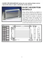
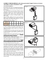
When the circuit board verifies all four basic controls have
been satisfied (control humidistat, high limit humidistat,
air flow, door interlock), a signal is sent to open a fill
solenoid valve, allowing water to flow across an air gap
into a standpipe. The standpipe provides a column of
water to be fed into the cylinder using gravity. The air gap
prevents the cylinder from pressurizing.
See Figure Q
.
The steam cylinder normally operates at a pressure of
approximately 1/2 psi.
STEAM
DISTRIBUTOR
PIPE
STEAM
HOSE
FROM POWER
CONTACTOR
CYLINDER
VERTICAL
ELECTRODES
DRAIN
SOLENOID
VALVE
TO DRAIN
STEAM
WATER
AIR GAP
FILL
SOLENOID VALVE
NON CONTACT
HIGH WATER
SENSOR
Figure Q
STAND
PIPE
OVERFLOW
TUBE
CONTROL CONNECTIONS
FOR SAFETY:
MAKE SURE TO TURN OFF POWER AT THE
EXTERNAL DISCONNECT BEFORE MAKING ANY INTERNAL
CHANGES TO THE HUMIDIFIER.
1. A 7/8” opening is provided on the top or bottom of the cabinet.
The control wiring should pass through the opening to the
provided connection points at J16, J17, and J18.
2. If an air flow switch or high limit humidistat is not used,
jumpers must be installed before the humidifier will operate.
On J17, jump terminals 2 and 4 together to bypass the high
limit. On J18, jump terminals 1 and 2 together to bypass the
air flow switch.
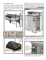
EXTERNAL MONITORING
Pins 1 and 2 of connector J10, shown in
Photo H
, are provided for
indicating operation of the humidifier at a remote location. When
the unit is operating, pins 1 and 2 (EXT PWR) are closed. Pins
3 and 4 of connector J10 (EXT SRV) are provided to indicate
the need for service. A “Service Required” warning on the home
screen of the LCD will indicate the type of service that is needed.
Both the EXT PWR and EXT SRV relays have a maximum ratings
of 0.3A at 125VAC or 1A at 24VDC maximum.
CarnesLink is an option to have full external monitoring and
control of your Carnes humidifier(s) by allowing the humidifier(s)
to link to a Building Management System (BMS) using one of the
following protocols: BACnet® (MS/TP), Modbus® (RTU),
Metasys® (N2) and Siemens® (FLN).The user friendly interface
on the True Touchscreen makes setting up CarnesLink easy
and convenient. (See the CarnesLink Communication Protocol
Installaion, Operation, and Maintenance Manual for further info.)
NETWORKING
If multiple units are required due to high capacity demand
(over 200 lb. per hour, single unit), networking can be done.
Units can be interconnected with parallel signal wiring. This setup
is usually done to facilitate running multiple units from a single
signal control (Humidistat, BMS System, etc.). For other
networking requirements, please contact factory.
As mineral deposits build up within the cylinder the water
level will slowly rise to uncovered electrode surfaces to
maintain the desired steam output rate. When mineral
deposits have covered all available electrode surfaces,
current flow will be reduced to a level where the desired
steam output cannot be reached and the service light will
signal the need for maintenance. When the cylinder is filled
with minerals it is easily changed in less than five minutes
(not including cool down time).
Important Note:
Due to the many variables effecting the
operation of humidifiers (water condition, conductivity,
hardness, etc.) it could take up to 24 hours of operation
before a humidifier is truly operating normally and the water
is completely conditioned. Conditioned water is a state
where the amount of minerals dissolved within the water
is at a steady state. Conditioned water is more conductive
than new water from the fill valve.
The circuit board also closes a power contactor allowing
current to flow to vertical electrodes sealed inside the
cylinder. Current flows between the electrodes using
minerals in the water as a conductor. The water is heated
to boiling and converted to steam which leaves the cylinder
through the flexible steam hose which is connected to the
steam distributor pipe.
The circuit board reacts to current flow between the
electrodes and automatically opens the fill solenoid valve
when more water is required to maintain the desired
output rate and closes when the desired rate is reached.
The operation of the drain solenoid valve is automatically
controlled by the circuit board which responds to any
changes in water conditions and drains the required
quantity of water to provide stable operation and long
cylinder life.
Photo H


