Maintenance
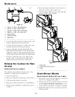
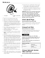
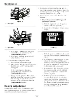
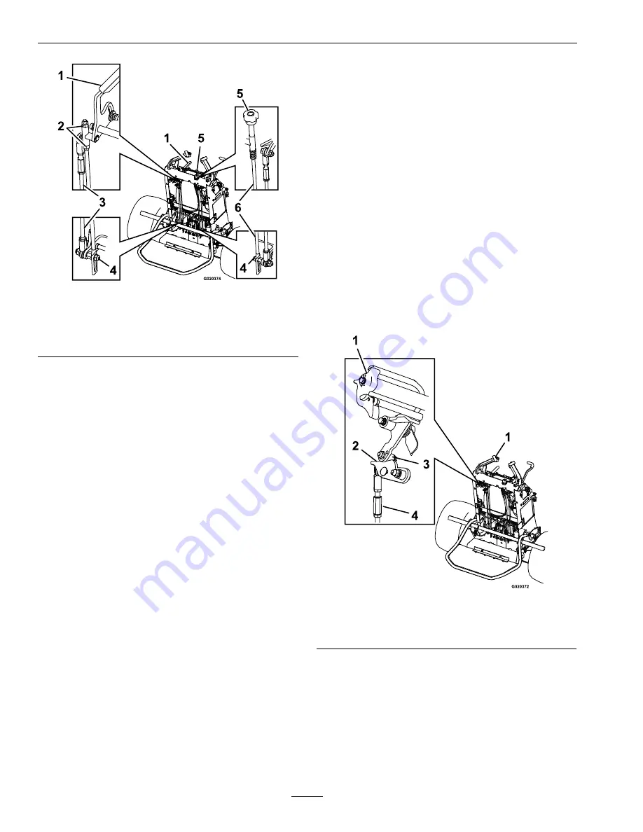
Figure 36
1.
Speed control lever
4.
Stud
2.
Nut
5.
Tracking knob
3.
Speed control rod
6.
Tracking rod
d. Pull the speed control lever into the full
back (neutral) position.
e. Allow the speed control rod to sit on the
stud.
f. Adjust and tighten the nuts.
Note:
Make sure the flat of the rod is
perpendicular to the stud.
g. Adjust the tracking rod by turning tracking
knob until the rod is sitting on the stud
(reference Figure 36).
h. Start the engine and release the parking
brake.
i.
Move either OPC lever to the operating
position.
j.
Move the speed control lever to the full
forward and then back to neutral to make
sure wheels are not turning. Check with
the neutral lock latches engaged and
disengaged.
k. Check the tracking and adjust as needed
(see
Tracking Adjustment
section).
D.
Neutral Ramp Adjustment:
Note:
This adjustment should only be needed
if components have been replaced or if neutral
lock and neutral detent are not aligned. Adjust
the speed control lever and drive wheels
before performing this adjustment.
a. Stop engine and wait for all moving parts
to stop.
b. Place the speed control lever into the full
back (neutral) position.
c. Remove the steering rod from the ramp
arm.
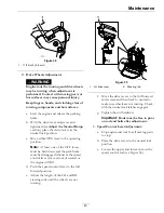
d. Place the drive levers in the neutral lock
position (see Figure 8).
e. Rotate the ramp arm into a position where
the ramp contacts the roller. Note this
position.
f. Loosen the ramp retaining bolt and slide
the ramp until both forward and reverse
ramp surfaces contact the roller. Tighten
the ramp hardware.
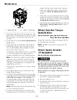
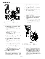
Figure 37
1.
LH drive lever
3.
Roller
2.
Drive lever ramp surface
4.
Steering rod
g. Make this adjustment on both sides.
h. Check the neutral location by moving the
drive levers from forward to neutral. Stop
when a change in force into the detent is
felt. The thumb lock lever should easily
engage with little steering movement; there
should not be a gap between the lock latch
and the drive lever.
44
Содержание VANTAGE X Series
Страница 1: ...VANTAGE X SERIES For Serial Nos 315 000 000 Higher Part No 4502 224 Rev A ...
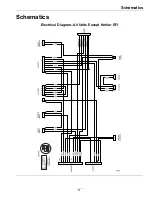
Страница 51: ...Schematics Schematics Electrical Diagram All Units Except Kohler EFI 51 ...
Страница 52: ...Schematics Electrical Diagram Kohler EFI 52 ...
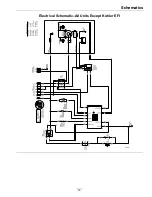
Страница 53: ...Schematics Electrical Schematic All Units Except Kohler EFI 53 ...
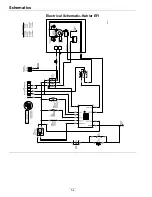
Страница 54: ...Schematics Electrical Schematic Kohler EFI 54 ...
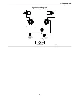
Страница 55: ...Schematics Hydraulic Diagram 55 ...
Страница 57: ...Service Record Date Description of Work Done Service Done By 57 ...
Страница 58: ...58 ...

