Maintenance
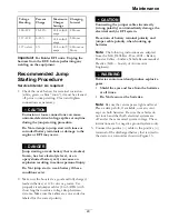
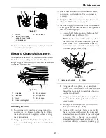
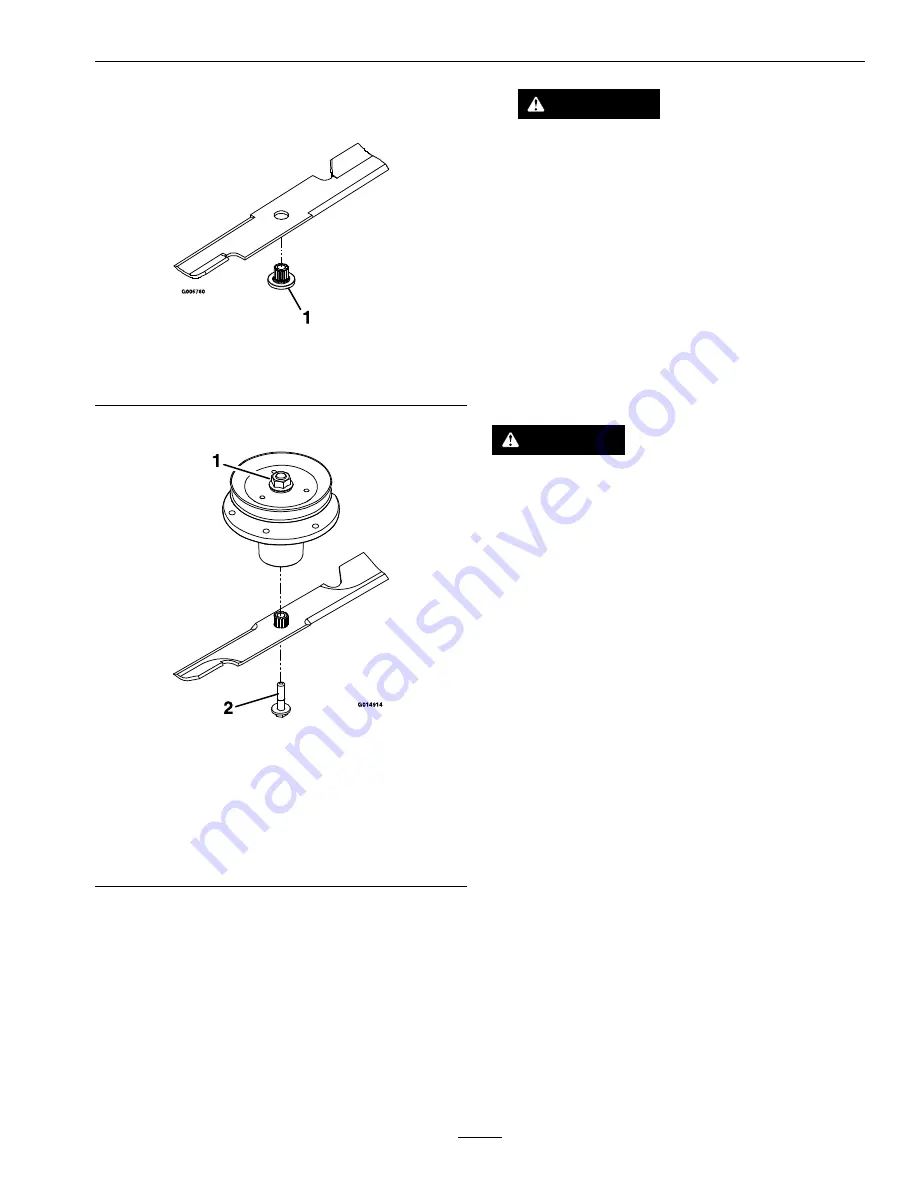
A. Install bushing through blade with bushing
flange on bottom (grass) side of blade.
Figure 15
1.
Install bushing in blade prior to installing bushing in
spindle.
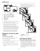
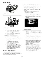
B. Install bushing/blade assembly into spindle.
Figure 16
1.
Use wrench here for
blade installation. This
nut has been torqued to
130-160 ft-lb (176–217
N-m)
2.
Torque to 50-60 ft-lb
(68-81 N-m) Apply
lubricant to threads
as needed to prevent
seizing. Copper-based
anti-seize preferable.
Grease acceptable
substitute.
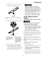
C. Apply lubricant to threads of blade bolt as
needed to prevent seizing. Copper-based
anti-seize preferable. Grease acceptable
substitute. Install blade bolt finger tight. Place
wrench on the top spindle nut then torque the
blade bolts to 50-60 ft-lb (68-81 N-m).
WARNING
Incorrect installation of the blade or
components used to retain the blade can
be dangerous. Failure to use all original
components and assembled as shown could
allow a blade or blade component to be
thrown out from under the deck resulting in
serious personal injury or death.
Always install the original Exmark blades,
blade bushings, and blade bolts as shown.
Check Safety Interlock
System
Service Interval: Before each use or daily
CAUTION
If safety interlock switches are disconnected
or damaged the machine could operate
unexpectedly causing personal injury.
•
Do not tamper with the interlock switches.
•
Check the operation of the interlock switches
daily and replace any damaged switches
before operating the machine.
Understanding the Safety Interlock System
The safety interlock system is designed to prevent
the mower blades from rotating; unless at least one
of the OPC levers is engaged and the blade control
switch (PTO) is pulled
on
.
The safety interlock system is designed to stop the
mower blades if you release both OPC levers.
Note:
Park brake must be disengaged before the
speed control lever is moved out of neutral or engine
will kill.
Checking the Safety Interlock System
1. Start the engine.
2. Engage the parking brake.
3. Move either OPC lever to the operating position
and push the speed control lever forward.
The engine should initiate shutdown after
momentary pause.
4. Start the engine and release the parking brake.
5. Move either OPC lever to the operating position.
6. Continue holding the either OPC lever in the
operating position and pull up on the blade
31
Содержание VANTAGE X Series
Страница 1: ...VANTAGE X SERIES For Serial Nos 315 000 000 Higher Part No 4502 224 Rev A ...
Страница 51: ...Schematics Schematics Electrical Diagram All Units Except Kohler EFI 51 ...
Страница 52: ...Schematics Electrical Diagram Kohler EFI 52 ...
Страница 53: ...Schematics Electrical Schematic All Units Except Kohler EFI 53 ...
Страница 54: ...Schematics Electrical Schematic Kohler EFI 54 ...
Страница 55: ...Schematics Hydraulic Diagram 55 ...
Страница 57: ...Service Record Date Description of Work Done Service Done By 57 ...
Страница 58: ...58 ...

