- 20 -
IMPORTANT: For electric start models, do not crank the engine continuously
for more than ten (10) seconds at a time. If the engine does not start, allow a
60 second starter cool-down period between starting attempts. Failure to
follow these guidelines can burn out the starter motor.
On a warm engine, place the throttle control
midway
between the “Slow” and
“Fast” positions.
After engine warms up, gradually push in the choke control.
DO NOT
run a
warm engine with the choke in the “ON” position.
NOTE: Kawasaki engines generally need to be “choked” even when warm.
4.3.3
Stopping Engine: Lock the drive levers in neutral, disengage PTO, position
speed control lever in neutral, and engage the park brake. Place the throttle
control
midway
between the “slow” and “fast” positions. Allow the engine to run
a minimum of 15 seconds; then turn the key to the “Off” position.
Close the fuel shut off valve if machine will
not
be used for a few days; when
parking inside a building; or when transporting the unit.
4.3.4
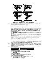
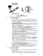
Drive Lever/Neutral Lock Latch Operation:
To lock the drive levers in “
neutral lock
”, squeeze the drive levers back to the
“
neutral
” position. See Figure 6 (a). (
Do Not
squeeze the drive levers all the
way back as this will cause the drive wheels to go into full reverse direction
).
Place thumbs on the inner thumb lobe of the neutral lock latches and rotate them
to the “neutral lock” position. See Figure 6 (b). Release drive levers.
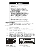
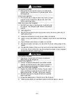
CAUTION
POTENTIAL HAZARD
♦
If the neutral lock latches are not completely engaged
the drive levers could unexpectedly slip into the
forward drive position.
WHAT CAN HAPPEN
♦
If the drive levers slip into the drive position, the unit
could lurch forward and cause injury or property
damage.
HOW TO AVOID THE HAZARD
♦
Be sure the drive levers are past the roller and
securely seated at the bottom of the neutral lock
latches.
To place the drive levers in the “
forward
” position, slightly squeeze the drive
levers while placing thumbs on the outer thumb lobe of the neutral lock latches
(or the index finger on the inner lobe) and rotate them from under the drive
levers.
Slowly
and
carefully
release the drive levers. See Figure 6 (d).
To place the drive levers in the “
reverse
” position, squeeze the drive levers past
the neutral position. See Figure 6 (c).
Содержание TT4819KAC
Страница 1: ...For Serial Nos 440 000 Higher Part No 103 4871 ...
Страница 44: ... 39 8 WIRING DIAGRAMS ...
Страница 45: ... 40 9 HYDRAULIC DIAGRAM ...

