Service Manual_AVA1_ENG-20220922_I
235
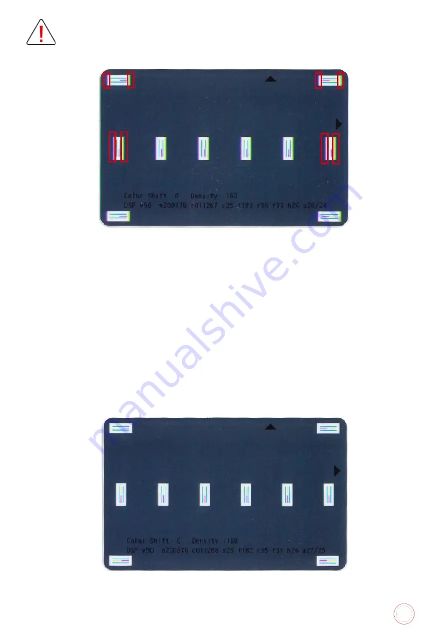
Same settings exist for both card side Adjustment >> Position >> Color Shift HRZ >> Shift HRZ
Back >> Print Test D-B. Each side should be set by application of the following steps.
On this example, we can notice magenta on left hand side of the areas and yellow on right hand side of
the areas. Also, the 2 Yellow and Magenta short lines are not lined up as it is supposed to.
On this example:
-
Magenta panel shift towards right hand side => decrease M Shift Hrz value
-
Yellow panel shifts towards left hand side => increase Y Shift Hrz value.
As same settings are available for both card sides, possible settings are the following:
-
Y Shift Hrz-F: sets Yellow panel position for card front
-
M Shift Hrz-F: sets Magenta panel position for card front
-
C Shift Hrz-F: sets Cyan panel position for card front
-
Y Shift Hrz-B: sets Yellow panel position for card back
-
M Shift Hrz-B: sets Magenta panel position for card back
-
C Shift Hrz-B: sets Cyan panel position for card back
Once fixed, Test card should be as following:
Содержание AV1H0000BD
Страница 1: ...Service Manual_AVA1_ENG 20220922_I 1 AVANSIA SERVICE MANUAL...
Страница 68: ...Service Manual_AVA1_ENG 20220922_I 68 Drawing 4 CLEANING TAPE CASSETTE S10198 CLEANING ROLLER S10197...
Страница 69: ...Service Manual_AVA1_ENG 20220922_I 69 Drawing 5 PUSHING BLADE CP012087 SPRING PLATE SENSOR CP012327...
Страница 73: ...Service Manual_AVA1_ENG 20220922_I 73 Drawing 9 HEAT ROLLER CP011845 HEAT ROLLER MODULE S10248...
Страница 74: ...Service Manual_AVA1_ENG 20220922_I 74 Drawing 10 DECURL MODULE CP011976 DECURL SPRING CP011978...
Страница 75: ...Service Manual_AVA1_ENG 20220922_I 75 Drawing 11 ROLLER PRINT PLATEN CP013457 ROLLER FILM CP013659...
Страница 76: ...Service Manual_AVA1_ENG 20220922_I 76 Drawing 12 PACKAGING BOX AND FOAM S10205...
Страница 109: ...Service Manual_AVA1_ENG 20220922_I 109 Tools required...
Страница 111: ...Service Manual_AVA1_ENG 20220922_I 111 Step 2 REAR TOP COVER CP011784 1 Remove the four screws 2 Remove the two screws...
Страница 117: ...Service Manual_AVA1_ENG 20220922_I 117 4 Rear side remove the two screws 5 Open the cables holder...
Страница 118: ...Service Manual_AVA1_ENG 20220922_I 118 6 Move the hinge outwards 7 Remove the two screws...
Страница 119: ...Service Manual_AVA1_ENG 20220922_I 119 8 Lift the metal plate to the left 9 Disengage it from the front side cover...
Страница 120: ...Service Manual_AVA1_ENG 20220922_I 120 10 Disengage the front side cover 11 Carry out the steps in reverse...
Страница 125: ...Service Manual_AVA1_ENG 20220922_I 125 1 Remove the four screws 2 Remove the screw of the ground spring blade...
Страница 133: ...Service Manual_AVA1_ENG 20220922_I 133 8 Unplug the two sensors 9 Remove the three screws...
Страница 135: ...Service Manual_AVA1_ENG 20220922_I 135 12 Remove the heat roller horizontally...
Страница 139: ...Service Manual_AVA1_ENG 20220922_I 139 6 Remove the V ring 7 Remove the axis...
Страница 140: ...Service Manual_AVA1_ENG 20220922_I 140 8 Cut the cable clamp 9 Remove the two screws and the plastic film...
Страница 152: ...Service Manual_AVA1_ENG 20220922_I 152 5 Open the cables holder 6 Remove the screw of the sensor support...
Страница 153: ...Service Manual_AVA1_ENG 20220922_I 153 7 Disengage gently the sensor support 8 Unplug the sensor cable...
Страница 154: ...Service Manual_AVA1_ENG 20220922_I 154 9 Unclip the sensor and remove it 10 Carry out the steps in reverse...
Страница 158: ...Service Manual_AVA1_ENG 20220922_I 158 7 Remove the two screws...
Страница 159: ...Service Manual_AVA1_ENG 20220922_I 159 8 Disengage gently the sensors support 9 Unclip the broken sensor...
Страница 167: ...Service Manual_AVA1_ENG 20220922_I 167 13 Unplug these cables 14 Open the cables holder...
Страница 168: ...Service Manual_AVA1_ENG 20220922_I 168 15 Find and unplug these two cables 16 And unplug these one...
Страница 170: ...Service Manual_AVA1_ENG 20220922_I 170 19 Remember the decurl spring position 20 Remove the plastic V ring...
Страница 176: ...Service Manual_AVA1_ENG 20220922_I 176 4 Remove the screw and the head cable from the holder 5 Unplug the head cable...
Страница 177: ...Service Manual_AVA1_ENG 20220922_I 177 6 Reconnect the head and put the head support back 7 Put the screw back...
Страница 179: ...Service Manual_AVA1_ENG 20220922_I 179 10 Plug the print head cable 11 Put the print head cover back and its screw...
Страница 202: ...Service Manual_AVA1_ENG 20220922_I 202 16 Close the feeder a and the top cover b Your printer is ready to use b a...
Страница 205: ...Service Manual_AVA1_ENG 20220922_I 205 6 Put back cleaning tape cassette blue part 7 Close the front cover...
Страница 221: ...Service Manual_AVA1_ENG 20220922_I 221 8 Close the front cover...
Страница 242: ...Service Manual_AVA1_ENG 20220922_I 242 COLORED WRINKLES Colored wrinkles are visible on card surface...
Страница 274: ...Service Manual_AVA1_ENG 20220922_I 274 Maintenance tab Printing test Evolis card printer graphical test card...
Страница 275: ...Service Manual_AVA1_ENG 20220922_I 275 Printer details Ribbon details...
Страница 286: ...Service Manual_AVA1_ENG 20220922_I 286 BLOCK PLAN FOR ELECTRIC PARTS...
Страница 287: ...Service Manual_AVA1_ENG 20220922_I 287...
Страница 288: ...Service Manual_AVA1_ENG 20220922_I 288...
Страница 289: ...Service Manual_AVA1_ENG 20220922_I 289...
Страница 290: ...Service Manual_AVA1_ENG 20220922_I 290...
Страница 291: ...Service Manual_AVA1_ENG 20220922_I 291 MAIN BOARD PLAN...
Страница 293: ...Service Manual_AVA1_ENG 20220922_I 293 www evolis com...


