65
CONFIGURATION PARAMETERS
►
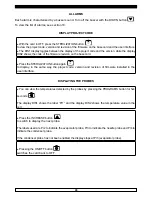
-Put the display in OFF, press for 5 seconds the UP
and DOWN
buttons.
The display DIS1 shows the first parameter (the first label is PA: Password) The display DIS2
shows the parameters value.
Scroll the parameters list with the UP
and DOWN
buttons.
Edit each parameters with the PROGRAM
button, the LED associated with the key lights.
►
Change the value with the UP
and DOWN
buttons, confirm with the PROGRAM
buttons.
►
GET BACK TO THE OFF status pressing the UP
and DOWN
buttons for 5 seconds
or do not operate for 15 seconds.
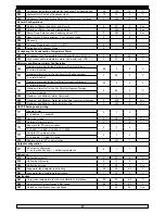
PARAMETERS
LABEL DESCRIPTION
MIN
MAX
DEFAULT
U.M.
Temperatures
P0
Selects the measuring units for temperature
0
1
1
-
1 = Celsius
0 = Fahrenheit
P1
Cell probe offset
-10
10
0
°C
P2
Evaporator probe offset
-10
10
0
°C
P3
Needle probe offset
-10
10
0
°C
Adjustment Setpoint
P4
Blast chilling Cell Temperature Setpoint
-40
99
-2
°C
P5
Cell Temperature Setpoint for Freezing
-40
99
-40
°C
P6
Cell Temperature Setpoint for first Hard Cycle phase
-40
P4
-20
°C
P7
Cell Setpoint for Positive storage
-40
99
3
°C
P8
Cell Setpoint for Negative storage
-40
99
-20
°C
P9
Adjustment hysteresis
1
15
2
°C
P10
Needle Probe Temperature for end of Blast chilling
-40
99
3
°C
P11
Needle Probe Temperature for end of Freezing
-40
99
-18
°C
P12
Needle Probe Temperature pin for End of first Hard cycle
P10
99
15
°C
P13
Needle Probe Temperature Threshold for start of Decrease in time
-40
99
65
°C
Needle probe insertion
P14
Temperature Difference between Needle probe and Cell for ins.
Needle probe
0
99
0
°C
P15
Needle probe Insertion Differential Test duration
1
99
60
Sec
Cycles Duration
P16
Temperature Cycle Duration
1
400
90
Min
P17
Freezing Cycle Duration
1
400
240
Min
P18
Duration of First Hard phase for Time Cycle
1
P16
20
Min
Compressor safety times
P19
Compressor Start Delay from Power On
0
99
0
Min
P20
Minimum time between two compressor starts
0
99
0
Min


