background image

43

ENGLISH

After the adjustment is finished, do not operate the instrument for 60 seconds, it will automatically 

exit the procedure

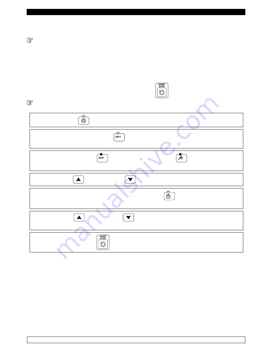
 9.2.3 Selecting cycles (fig.3) 

With card in STANDBY: you can select a blast chilling/freezing cycle. The cycles can be controlled 

by the temperature of the needle probe or by a time. Where they are controlled by the temperature 

of the needle probe, the end of the blast chilling phase occurs when the needle probe reaches the 

setpoint at the end of blast chilling/freezing, while if a duration is defined for the blast chilling/freezing 

phase, the end occurs when the preset time expires. 

For both types of cycle, once the blast chilling/freezing phase ends, the storage phase starts, the end 

of which is defined by pressing the START/STOP button,  

, which puts the card in STANDBY

 POSITIVE BLAST CHILLING CYCLE 

► 

Press the ON/OFF 

 button 

► 

Press the BLAST CHILLING button 

 to select a positive blast chilling cycle. By default, the 

selected cycle is controlled by the temperature of the needle probe.

► 

The BLAST CHILLING LED 

  and the TEMPERATURE LED 

  are on. The display DIS1 

shows the cell setpoint, while the display DIS2 shows three dashes. 

► 

The INCREASE  

  and DECREASE 

 buttons can be used to change the cell setpoint. 

► 

To switch the cycle to a time cycle, press the TIME button 

 . 

The display DIS2 shows the time.

► 

The INCREASE  

  and DECRASE 

  buttons can be used to change the time .

The changes made are only temporary and are not saved.

► 

Pressing the START/STOP 

 button starts the execution of the cycle.

NOTE: 

The minimum acceptable value for the cell setpoint is -2°C and the maximum is 99°C.  

The minimum value that can be set for the time is 0 minutes, the maximum is 400 minutes.

Содержание PROF ABF 05

Страница 1: ...ABBATTITORI SURGELATORI RAPIDI BLAST CHILLERS SHOCK FREEZERS PROFESSIONAL TRAY Manuale d uso e manutenzione Use and maintenance manual Rev 3 10 2016 ...

Страница 2: ...urgelamento Modello Raffreddamento rapido 90 C 3 C Surgelamento rapido 90 C 18 C PROF ABF 05 22 Kg 14 Kg PROF ABF 10 35 Kg 25 Kg PROF ABF 15 55 Kg 35 Kg PROF ABF 20 75 Kg 55 Kg N B i tempi e le quantità in Kg sopra indicati sono validi per prodotti con spessore massimo di 4 cm Tempo massimo Raffreddamento positivo entro 90 min Surgelazione entro 240 min L abbattitore di temperatura è conforme alle...

Страница 3: ...gnerlo ed astenersi da qualsiasi tentativo di riparazione o di intervento diretto E necessario rivolgersi esclusivamente a personale qualificato L abbattitore di temperatura è costituito da una monoscocca modulare rivestita con materiali diversi e isolata con poliuretano espanso a densità 42 kg m3 In fase di progettazione e realizzazione sono stati adottati tutti gli accorgimenti per ottenere un a...

Страница 4: ...i conservati IMPORTANTE Pulire frequentemente le guarnizioni delle porte Alcuni prodotti conservati protrebbero rilasciare degli enzimi che attaccano la guarnizionedeteriorandolamoltovelocemente Perlapuliziautilizzareprodotti specifici disponibili a richiesta anche presso la nostra rete commerciale 2 2 Pulizia del condensatore L efficienza dell abbattitore di temperatura è compromessa dall intasam...

Страница 5: ...zioni magnetiche secondo le indicazioni riportate al capitolo 2 lasciare le porte semiaperte per evitare il ristagno d aria e umidità residua CAPITOLO 4 MANUTENZIONE PREVENTIVA 4 1 Riavvio dopo lunga inattività Il riavvio dopo lunga inattività è un evento che richiede un intervento di manutenzione preventiva E necessario eseguire una accurata pulizia come descritto nel capitolo 2 4 2 Controllo dei...

Страница 6: ...itolo 1 resistenza sbrinamento guasta contattare assistenza tecnica sonda sbrinamento in avaria ER1 contattare assistenza tecnica ristagno di acqua o ghiaccio nel goc ciolatoio scarico ostruito pulire la pipetta e lo scarico abbattitore di temperatura non livellato verificare livellamento CAPITOLO 7 ISTRUZIONI PER LA RICHIESTA DI INTERVENTI Per qualsiasi problema di carattere tecnico e le eventual...

Страница 7: ...ta applicatasullaprotezionedell evaporatoreevicinoalcablaggioelettricoall interno del vano motore che avverte di escludere l alimentazione prima di intervenire sull apparecchio 3 rimuovere le targhette applicate all interno del vano motore indicanti la messa a terra 4 rimuovere la targhetta applicata sul cavo di alimentazione indicante il tipo di alimentazione 5 Il fabbricante declina qualsiasi re...

Страница 8: ...teglie troppo lontane dall evaporatore NO OK Evitare di concentrare in un unica zona dell abbattitore di temperatura le teglie in caso il carico non sia completo ma distribuirlo in altezza in modo omogeneo NO OK In caso di interruzione del circuito di alimentazione elettrica o di guasto evitare l apertura delle porte allo scopo di mantenere una temperatura omogenea all interno dell abbattitore di ...

Страница 9: ... pressione singola seleziona un ciclo di sterilizzazione Optional SBRINAMENTO Con scheda in STANDBY la pressione singola seleziona ed avvia un ciclo di sbrinamento HACCP Con scheda in OFF la pressione continua per cinque secondi permette di visualizzare lo storico allarmi Con storico allarmi visualizzato la pressione singola permette di stampare lo storico START STOP Concicloselezionato lapression...

Страница 10: ...to positivo SOFT HARD Con scheda in STANDBY la pressione singola permette di selezionare un ciclo di raffreddamento positivohard Conciclohardselezionato lapressione continua per cinque secondi permette di visualizzare il setpoint cella della seconda fase del ciclo Display temperatura Con scheda in OFF visualizza la label OFF Con scheda in STANDBY visualizza la temperatura in cella Dopo un interruz...

Страница 11: ...o di sbrinamento manuale lampeggiante durante il conteggio dei tempi di sgocciolamento Led HACCP Acceso durante la visualizzazione dello storico allarmi Led START STOP Acceso durante l esecuzione di un ciclo lampeggiante durante la conservazione Led PROGRAMMI Acceso se si è in impostazione selezione programmi e durante l esecuzione di uno dei 99 programmi Led SURGELAZIONE TEMPO Acceso se è selezio...

Страница 12: ...era interrotto e il display DIS1 visualizza la label PF lampeggiante per indicare che si è verificata una mancanza di tensione Se prima della mancanza di tensione non era in corso un ciclo il display DIS1 visualizza la temperatura della sonda cella mentre il display DIS2 visualizza tre trattini in questo caso la scheda è in STANDBY si può selezionare un ciclo ed avviarne l esecuzione Con scheda in...

Страница 13: ...ese Premere i tasti INCREMENTO e DECREMENTO per impostare il mese Premere il tasto TEMPO per passare all impostazione del giorno Premere i tasti INCREMENTO e DECREMENTO per impostare il giorno Premere il tasto TEMPO per passare all impostazione dell ora Premere i tasti INCREMENTO e DECREMENTO per impostare l ora Premere il tasto TEMPO per passare all impostazione dei minuti Premere i tasti INCREME...

Страница 14: ...da in STANDBY CICLO DI RAFFREDDAMENTO A TEMPERATURA POSITIVA Premere il tasto ON OFF La pressione del tasto RAFFREDDAMENTO permette di selezionare un ciclo di raffreddamento positivo Di default il ciclo selezionato è controllato dalla temperatura dello spillone Il led RAFFREDDAMENTO e il led TEMPERATURA sono accesi Il display DIS1 visualizza il setpoint cella mentre il display DIS2 visualizza tre ...

Страница 15: ... setpoint cella della seconda fase tenere premuto per cinque secondi il tasto HARD il led HARD lampeggia ed il display DIS1 visualizza il setpoint cella della seconda fase Per commutare il ciclo in un ciclo a tempo premere il tasto TEMPO Il display DIS2 visualizza il tempo Con i tasti INCREMENTO e DECREMENTO si può modificare il tempo Tale valore non può superare il valore del parametro in quanto ...

Страница 16: ... C ed il massimo è 99 C Il valore minimo impostabile per il tempo è 0 minuti il massimo è 400 minuti CICLO DI SURGELAZIONE A TEMPO La pressione del tasto SURGELAZIONE TEMPO permette di selezionare un ciclo di raffreddamento negativo a tempo Il led SURGELAZIONE TEMPO è acceso Il display DIS1 visualizza il setpoint temperatura cella mentre il display DIS2 visualizza il tempo Con i tasti INCREMENTO e...

Страница 17: ...ONE PESCE Premendo il tasto PROGRAMMI Premendo a questo punto il tasto INCREMENTO si seleziona la funzione di Sanificazione Pesce SAn Il display DS1 visualizza la label SAn il display DS2 visualizza tre trattini La pressione del tasto START STOP permette di avviare il ciclo La sanificazione pesce prevede l esecuzione di tre cicli il primo con controllo sulla temperatura sonda spillone il secondo a...

Страница 18: ...to viene cancellato e riscritto Sono disponibili 99 programmi 9 2 5 Selezione programmi Per richiamare un programma memorizzato premere il tasto PROGRAMMI Il display DIS1 visualizza P 1 Con i tasti INCREMENTO e DECREMENTO si seleziona il programma desiderato La pressione del tasto START STOP avvia l esecuzione del programma Durante l esecuzione del programma è possibile vedere il numero del progra...

Страница 19: ...to RAFFREDDAMENTO La visualizzazione permane sul display per cinque secondi Durante un ciclo a tempo è possibile visualizzare la temperatura della sonda spillone premendo il tasto SPILLONE La visualizzazione permane sul display per cinque secondi Quando la temperatura dello spillone raggiunge il valore definito per un ciclo a temperatura o scade il tempo impostato per un ciclo a tempo il ciclo di ...

Страница 20: ... permane sul display per cinque secondi Durante un ciclo a tempo è possibile visualizzare la temperatura della sonda spillone premendo il tasto TEMPERATURA La visualizzazione permane sul display per cinque secondi Quando la temperatura dello spillone raggiunge il setpoint o scade il tempo impostato per un ciclo a tempo la prima fase termina ed avviene automaticamente il passaggio alla seconda che ...

Страница 21: ...one permane sul display per cinque secondi Durante un ciclo a tempo è possibile visualizzare la temperatura della sonda spillone premendo il tasto TEMPERATURA La visualizzazione permane sul display per cinque secondi Quando la temperatura dello spillone raggiunge il valore definito per un ciclo a temperatura o scade il tempo impostato per un ciclo a tempo la fase di raffreddamento negativo termina...

Страница 22: ...il valore del parametro o scade il timeout Durante l esecuzione di un ciclo di sbrinamento si accende il led SBRINAMENTO ed il display DIS1 visualizza la label DEF Il ciclo di raffreddamento surgelazione inizia solo dopo la conclusione del ciclo di sbrinamento NOTA Se si verifica un allarme sonda evaporatore lo sbrinamento viene eseguito comunque e il termine è dato dallo scadere del timeout Sbrin...

Страница 23: ...lone Sonda Spillone guasta Sostituire la sonda Er4 Errore sonda Condensatore Sonda condensatore guasta Sostituire la sonda HP Allarme alta pressione tutti i cicli vengono bloccati Condensatore sporco Prodotto inserito troppo caldo Pulizia condensatore Raffreddare prodotto LP Allarme bassa pressione tutti i cicli vengono bloccati Carica gas ridotta Circuito frigorifero ostruito Service Service HA A...

Страница 24: ...ni relative ad ogni singolo allarme premere il tasto PROGRAMMI Per visualizzare l allarme successivo della lista premere il tasto INCREMENTO Per visualizzare l allarme precedente premere il tasto DECREMENTO La pressione del tasto ON OFF fa tornare la scheda in OFF Il numero massimo di minuti visualizzabile è 999 corrispondente a 16 ore e 39 minuti Se l allarme permane per un tempo superiore si vis...

Страница 25: ...lo si attiva automaticamente ad inizio ciclo di raffreddamento surgelazione Il report di stampa riporta la data il tipo di ciclo selezionato il campionamento ad intervalli regolari delle temperature di cella e prodotto i cicli di sbrinamento ed eventuali allarmi che si verificano durante il ciclo Per i dettagli degli allarmi vedere lo storico allarmi Esempio di Report di Stampa Tipo di ciclo Istan...

Страница 26: ...ello storico CAPITOLO 12 LIVELLO DI RUMOROSITA L abbattitore di temperatura è stato progettato e costruito in modo tale che i rischi dovuti all emissione di rumore aereo siano ridotti al livello minimo vedi schede tecniche CAPITOLO 13 MATERIALI E FLUIDI IMPIEGATI I materiali a contatto o che possono venire a contatto con i prodotti alimentari sono conformi alle direttive in materia L abbattitore d...

Страница 27: ...convenienti dovuti al trasporto effettuato in condizioni diverse da quelle specificate in precedenza Gli accessori a corredo dell abbattitore di temperatura guide griglie vaschette vassoi sono confezionati a parte e posizionati all interno del mobile L abbattitore di temperatura è fissato su un basamento di legno e protetto dagli urti accidentali con imballi in polietilene cartone gabbia o cassa P...

Страница 28: ...fonti di calore evitare l esposizione solare diretta rimuovere l imballo di polietilene cartone o legno Il polietilene è pericoloso per i bambini rimuovere eventuali accessori a corredo esterni Rimozione del basamento in legno Fig 4 sollevare e rimuovere il basamento Fig 4 utilizzare guanti di protezione nel maneggiare l imballo in legno e il basamento in legno La presenza di schegge potrebbe caus...

Страница 29: ...7 Fig 7 posizionare l abbattitore di temperatura come descritto sopra Fig 5 N B l impianto viene pressurizzato dal fabbricante con fluido di azoto predisporre i due tubi che fuoriescono dall abbattitore di temperatura per l allacciamento alle rispettive tubazioni collegare le tubazioni dell unità condensatrice alle tubazioni dell abbattitore di temperatura effettuare il vuoto e successivamente la ...

Страница 30: ...sostituzione può essere effettuata solo dal fabbricante o assistenza tecnica autorizzata E indispensabile collegare correttamente l abbattitore di temperatura ad un efficace impianto di messa a terra eseguito come previsto dalle vigenti disposizioni di legge CAPITOLO 16 OPERAZIONI DI MESSA A PUNTO E importante per prevenire errori ed incidenti eseguire una serie di controlli prima di avviare l abb...

Страница 31: ...collegare il cavo di alimentazione dalla presa di corrente la movimentazione va effettuata come descritto nel capitolo 14 per il nuovo piazzamento e allacciamento si rinvia ai par 14 1 procedere all eventuale recupero del gas refrigerante in accordo alle normative vigenti nel vostro paese ...

Страница 32: ...r freezing capacity in kg Model Blast chilling 90 C 3 C Rapid freezing 90 C 18 C PROF ABF 05 22 Kg 14 Kg PROF ABF 10 35 Kg 25 Kg PROF ABF 15 55 Kg 35 Kg PROF ABF 20 75 Kg 55 Kg N B the times and quantities in kg above are valid for products with a maximum thickness of 4 cm Maximum time Positive chilling 90 min Freezing 240 min TheblastchillercomplieswiththeEuropeandirectivesasdescribedindetailinth...

Страница 33: ...er turn it off and to refrain from any attempt to repair or intervene directly It is necessary to exclusively contact a qualified technician The blast chiller is composed of a modular monocoque coated with different materials and insulated with polyurethane foam of density 42 kg m3 In the design and construction all measures have been adopted to ensure a blast chiller that complies with safety and...

Страница 34: ...equencies depending on the type of food being stored REMARK Clean frequently the door seals Some preserved products could release some enzymes that could damage the seals causing its quick deterioration For the cleaning use only specific products for this purposes available also on request on our sales network 2 2 Cleaning the condenser The efficiency of the blast chiller is compromised by the clo...

Страница 35: ...joints and magnetic gaskets as indicated in Chapter 2 leave the door partly open to prevent air stagnation and residual humidity CHAPTER 4 PREVENTIVE MAINTENANCE 4 1 Restarting after a long period of inactivity Restarting after long inactivity is an event that requires preventive maintenance It is necessary to perform a thorough cleaning as described in chapter 2 4 2 Control of the warning and con...

Страница 36: ...cal support block of ice on the evaporator misuse see chapter 1 defrost heater fault contact technical support defrost probe damaged ER1 contact technical support accumulation of water or ice in the drip tray drain clogged clean the pipette and the drain blast chiller is not level check levelling CHAPTER 7 INSTRUCTIONS FOR REQUESTING ASSISTANCE For any technical problem and any requests for assist...

Страница 37: ...applied on the evaporator guard and near the electrical wiring inside the engine compartment which warns the user to turn off the power supply before working on the unit 3 to remove the labels applied inside the engine compartment indicating grounding 4 to remove the label applied on the power cord indicating the type of power supply 5 The manufacturer declines any responsibility for the safety of...

Страница 38: ...ce the trays too far away from the evaporator NO OK Do not concentrate the trays in one area of the blast chiller in case the load is not complete distribute its height evenly NO OK In case of interruption or failure of the power supply circuit prevent the opening of the doors in order to maintain a uniform temperature inside the blast chiller If the problem persists longer than a few hours it is ...

Страница 39: ...inuously for five seconds to put the card in OFF STERILIZATION With card in STANDBY pressing once selects a sterilization cycle Optional DEFROST With card in STANDBY pressing once selects and starts a defrost cycle HACCP With card in OFF press continuously for five seconds to view the alarms history With alarm history displayed press once to print the history START STOP With cycle selected press o...

Страница 40: ...cycle SOFT HARD With card in STANDBY pressing once allows you to select a positive blast chilling hard cycle With hard cycle selected press continuously for five seconds to display the cell setpoint of the second phase of the cycle Temperature display With card in OFF displays the label OFF With card in STANDBY displays the temperature in the cell After a power outage displays the flashing label P...

Страница 41: ...l defrost cycle flashing during the counting of draining times HACCP LED On while displaying the alarms history START STOP LED On during the execution of a cycle flashing during storage PROGRAMS LED On if you are setting selecting programs and during the execution of one of the 99 programs TIME FREEZING LED On if a negative blast chilling cycle freezing with time is selected FREEZING TEMPERATURE L...

Страница 42: ...esumed from the point at which it was interrupted and the display DIS1 will display the flashing label PF to indicate that there was a power failure If prior to the power failure there was no cycle in progress the display DIS1 shows the temperature of the cell probe while the display DIS2 shows three dashes in this case the card is in STANDBY you can select a cycle and execute it With card in OFF ...

Страница 43: ...NCREASE and DECREASE buttons to set the year Press the TIME button to switch to the month setting Press the INCREASE and DECREASE buttons to set the month Press the TIME button to switch to the day setting Press the INCREASE and DECREASE buttons to set the day Press the TIME button to switch to the hour setting Press the INCREASE and DECREASE buttons to set the hour Press the TIME button to switch...

Страница 44: ...by pressing the START STOP button which puts the card in STANDBY POSITIVE BLAST CHILLING CYCLE Press the ON OFF button Press the BLAST CHILLING button to select a positive blast chilling cycle By default the selected cycle is controlled by the temperature of the needle probe The BLAST CHILLING LED and the TEMPERATURE LED are on The display DIS1 shows the cell setpoint while the display DIS2 shows ...

Страница 45: ...l setpoint of the second phase hold the HARD button for five seconds the HARD led flashes and the display DIS1 shows the cell setpoint of the second phase To switch the cycle to a time cycle press the TIME button The display DIS2 shows the time The INCREASE and DECREASE buttons can be used to change the time This value cannot exceed the value of the parameter as this defines the total duration of ...

Страница 46: ... the maximum is 99 C The minimum value that can be set for the time is 0 minutes and the maximum is 400 minutes TIME FREEZING CYCLE Press the TIME FREEZING button to select a blast chilling cycle with negative time The TIME FREEZING LED is turned on The display DIS1 shows the cell temperature setpoint while the display DIS2 shows the time The INCREASE and DECREASE buttons can be used to change the...

Страница 47: ...T STOP button is pressed FISH SANITISATION CYCLE By pressing the PROGRAMS button the defrosting function is enabled By pressing the INCREASE button at this point the Fish Sanitisation function is selected The display DS1 SHOWS the label SAn The display DS2 shows three dashes Pressing the START STOP button allows you to start the cycle Fish sanification is carried out in three cycles the first is b...

Страница 48: ...tten it will be deleted and rewritten There are 99 programs available 9 2 5 Selecting programs To recall a stored program PROGRAMS The display DIS1 shows P 1 With the INCREASE and DECREASE buttons can be used to select the desired program Pressing the START STOP button starts the execution of the program When the program is running you can see the number of the program by pressing the PROGRAM butt...

Страница 49: ...NG button The visualisation remains on the displays for five seconds During a cycle with time you can view the temperature of the needle probe by pressing the NEEDLE PROBE button The visualisation remains on the displays for five seconds When the temperature of the needle probe reaches the value defined for a temperature cycle or the preset time expires for a time cycle the blast chilling cycle en...

Страница 50: ...on remains on the displays for five seconds During a time cycle you can view the temperature of the needle probe by pressing the TEMPERATURE button The visualisation remains on the displays for five seconds When the temperature of the probe reaches the setpoint or the preset time expires for a time cycle the first phase ends and is automatically switched to the second phase which ends when the tem...

Страница 51: ...sation remains on the displays for five seconds During a time cycle you can view the temperature of the needle probe by pressing the TEMPERATURE button The visualisation remains on the displays for five seconds When the temperature of the needle probe reaches the value defined for a temperature cycle or the preset time expires for a time cycle the negative blast chilling phase ends the buzzer soun...

Страница 52: ...obe exceeds the value of the parameter or the timeout expires During the running of a defrost cycle the DEFROST LED will turn on and the display DIS1 will show the label DEF The blast chilling freezing cycle starts only after the conclusion of the defrost cycle NOTE If an evaporator probe alarm occurs the defrost is performed however and the term is given by the expiration of the timeout Manual De...

Страница 53: ...r Evaporator probe fails Replace probe Er3 Core probe error you can not run cycles in probe Core probe fails Replace probe Er4 Condensator probe error Condensator probe fails Replace probe HP High pressure alarm all cycles are blocked Dirty condenser This product was added too hot Condenser cleaning Cool product LP Low pressure alarm all cycles are blocked Upload gas reduced Cooling circuit obstru...

Страница 54: ...ividual alarm press the PROGRAMS button To display the next alarm in the list press the INCREASE button To view the previous alarm press the DECREASE button Pressing the ON OFF button switches the card back to OFF The maximum number of minutes that can be displayed is 999 corresponding to 16 hours and 39 minutes If the alarm persists for a longer time 999 is displayed flashing in the place where t...

Страница 55: ...lated to a cycle is automatically activated at the beginning of the blast chil ling freezing cycle The printed report shows the date the type of cycle selected the sampling at regular intervals of the cell and product temperatures the defrost cycles and any alarms that occur during the cycle For details of the alarms see the alarms history Sample Print Report Type of cycle Sampling instants End of...

Страница 56: ...printing if no alarm is present in the history CHAPTER 12 NOISE LEVEL The blast chiller is designed and constructed so that risks resulting from the emission of airborne noise are reduced to the minimum level see technical information CHAPTER 13 MATERIALS AND FLUIDS USED The materials in contact or which may come into contact with foodstuffs comply with the relevant directives The blast chiller ha...

Страница 57: ...r disclaims any liability for problems resulting from transport performed under conditions other than those specified above The accessories of the blast chiller guides grilles trays are packaged separately and placed inside the unit Theblastchiller is mountedonawooden baseand protected from accidental impact with polyethylene carton crate or boxes Regarding the disposal of the packaging it is nece...

Страница 58: ... heat sources avoid exposure to direct sunlight remove the polyethylene cardboard or wood packaging Polyethylene is dangerous for children remove any accessories with external connections Removing the wooden base Fig 4 lift the blast chiller and remove the base Fig 4 use protective gloves when handling the wooden packaging and the wooden base The presence of splinters may cause damage to your hand...

Страница 59: ...last chillers Fig 7 Fig 7 position the blast chiller as described above Fig 5 N B the system is pressurized by the manufacturer with azoto prepare the two pipes that protrude from the temperature blast chiller for the connection to the respective pipes connect the pipes of the condensing unit to the pipes of the blast chiller create a vacuum and then carry out the loading of the refrigerant make t...

Страница 60: ... specified by the applicable provisions of law CHAPTER 16 INSTALLATION OPERATIONS It is important in order to prevent errors and accidents to perform a series of checks before starting up the blast chiller in order to identify any damage incurred during transport handling and connection Checks to be performed check the integrity of the power cord it must not have suffered abrasions or cuts check t...

Страница 61: ...he qualsiasi intervento eseguito da personale non tecnico o non autorizzato produrrà la decadenza delle condizioni di garanzia WARNING INSTRUCTIONS STRICTLY RESERVED TO AUTHORIZED TECHNICAL PERSONNEL Every intervention executed by a non authorized technical personnel implies a warranty decay ...

Страница 62: ...ra per temperatura 0 1 1 1 celsius 0 Fahrenheit P1 Offset sonda cella 10 10 0 C P2 Offset sonda evaporatore 10 10 0 C P3 Offset sonda spillone 10 10 0 C Setpoint di Regolazione P4 Setpoint Temperatura Cella Raffreddamento 40 99 2 C P5 Setpoint Temperatura Cella per Surgelazione 40 99 40 C P6 Setpoint Temperatura Cella per prima fase Ciclo Hard 40 P4 20 C P7 Setpoint Cella per conservazione Positiv...

Страница 63: ... C P33 Isterisi per riavvio Ventilatori 15 15 1 C P34 Abilita l uso ventole in Sbrinamento per P22 è uguale a zero o e uno 0 1 0 0 ventole ferme durante lo sbrinamento 1 ventole attive durante lo sbrinamento P35 Durata blocco ventole dopo lo sgocciolamento 0 15 1 Min P36 Soglia temperatura cella per Blocco Ventilatori 40 99 90 C P37 Effetto apertura Porta sui ventilatori 0 1 1 0 nessun effetto 1 a...

Страница 64: ...di Minima relativo al Set Point per Conservazione Positiva 99 0 0 C 0 allarme disabilitato P65 Set Allarme di Massima relativo al Set Point per Conservazione Positiva 0 99 0 C 0 allarme disabilitato P66 Set Allarme di Minima relativo al Set Point per Conservazione Negativa 99 0 0 C 0 allarme disabilitato P67 Set Allarme di Massima relativo al Set Point per Conservazione Negativa 0 99 0 C 0 allarme...

Страница 65: ...visualizzazione del codice progetto e della versione mentre il display DIS2 visualizza il codice della revisione del firmware presente nella scheda base La successiva pressione del tasto STERILIZZAZIONE visualizza nello stesso modo il codice progetto versione e revisione del firmware presente nell interfaccia utente VISUALIZZAZIONE SONDE E possibile visualizzare temperature rilevate dalle sonde pr...

Страница 66: ...rature Setpoint 40 99 2 C P5 Cell Temperature Setpoint for Freezing 40 99 40 C P6 Cell Temperature Setpoint for first Hard Cycle phase 40 P4 20 C P7 Cell Setpoint for Positive storage 40 99 3 C P8 Cell Setpoint for Negative storage 40 99 20 C P9 Adjustment hysteresis 1 15 2 C P10 Needle Probe Temperature for end of Blast chilling 40 99 3 C P11 Needle Probe Temperature for end of Freezing 40 99 18 ...

Страница 67: ... defrost P35 Duration of fans lock after draining 0 15 1 Min P36 Threshold temperature for Fans Lock cell 40 99 90 C P37 Door opening effect on the fans 0 1 1 0 no effect 1 stop fans Digital inputs P38 Door micro input polarity 0 1 0 0 NO 1 NC P39 Door opening signalling delay 0 200 0 Sec P40 High Pressure Alarm input polarity 0 1 1 0 NO 1 NC P41 High Pressure Alarm Input Delay 0 200 120 Sec P42 L...

Страница 68: ...for the Set Point for Negative Storage 99 0 0 C 0 alarm disabled P67 Maximum Alarm Set for the Set Point for Negative Storage 0 99 0 C 0 alarm disabled P68 Maximum and Minimum alarm Hysteresis 15 2 C P69 Maximum and Minimum Alarm Inhibition time from start of Storage 0 255 0 Min P70 Maximum and Minimum Alarm Inhibition time 0 255 0 Min HACCP Settings and printing P71 Enable Printer 0 1 0 0 disable...

Страница 69: ...ERILIZATION button again to display in the same way the project code version and revision of firmware installed in the user interface DISPLAYING THE PROBES You can view the temperatures detected by the probes by pressing the PROGRAMS button for five seconds The display DIS1 shows the label Pr1 and the display DIS2 shows the temperature value in the cell Press the INCREASE button to switch to displ...

Страница 70: ... 11 12 13 14 15 16 17 18 19 20 21 22 25 23 26 24 MARRONE BROWN BLU BLUE GIALLO VERDE YELLOW GREEN LG S CONNESSIONE TASTIERA ORIZZONTALE HORIZONTAL KEYBORD CONNECTION RS 485 STAMPANTE PRINTER OPTIONAL RS 485 INTERFACCIA UTENTE USER INTERFACE ...

Страница 71: ...SW2 SW4 POWER GND GND 12V 10 11 12 13 14 15 16 17 18 19 20 21 22 25 23 26 24 KS RS1RS2 RS3 MARRONE BROWN NERO BLACK GRIGIO GRAY BLU BLUE GIALLO VERDE YELLOW GREEN RS OPT CONNESSIONE TASTIERA ORIZZONTALE HORIZONTAL KEYBORD CONNECTION RS 485 STAMPANTE PRINTER OPTIONAL RS 485 INTERFACCIA UTENTE USER INTERFACE Components key CP Compressor K1 Compressor relay RP Anti condensate heater VC Condenser fan ...

Страница 72: ... 6500 4800 8900 Potenza max assorbita kw Max absorption kw 0 8 2 3 3 4 5 Tensione alimentazione Voltage 230 1 50 400 3N 50 400 3N 50 400 3N 50 Fluido refrigerante Kg Cooling gas Kg R404 A Kg 1 3 1 7 2 95 4 Peso unitario Unit Weight Kg 128 173 218 225 Peso del materiale imballato Kg Shipping Weight Kg Kg 140 185 230 238 L P H L P H L P H L P H Dimensioni esterne L x P x H mm External Dimension L x ...

Отзывы: