background image

OPERATING PRINCIPLES

I

1


- CLEANING CYCLE

I

1.2 - Cleaning of the Plastic Trough (35).
The plastic trough (35) will reach its maximum lower position to discharge the water from the last cycle which was 
interrupted by the shutdown of the Machine. This cleaning cycle is necessary due to safety and hygiene reasons, 
because we could not quantify the time that the Ice Machine is turned off, with water inside the plastic trough (35).

1.1 - Initialization
Every time the machine is energized (connected to the power grid, switched on again by the tank's thermostat 
(61) or after a power surge), the cleaning cycle for the plastic trough (35) and evaporator (20) starts up. The 
signaling LEDs - LD1 (maintenance), LD2 (water shortage) - for the circuit board (62) and the LED board (68), 
light up for a period of 02 seconds, in order to inform the start-up of the system's operation.

2


- ICE FORMATION CYCLE

2.1 - Formation
After the cleaning cycle, the plastic trough (35) returns to the highest position, the circuit board (62) switches on 
the water valve (63) to let water in the the plastic trough (35), the mobile water sensor (55) indicates to the 
circuit board (62) when the water level of the plastic trough (35) touches it, and switches off the water valve (63). 
With the cooling system in operation, the formation of ice around the cube makers in the evaporator begins (20), 
such cubes will grow to a thickness that obstructs the passage of the plastic fins (29) which rotate continuously

.

3


- ICE DETACHMENT CYCLE

The purpose of the tank thermostat (61), whose bulb is fixed below the equipment's water draining tray, is to 
switch the equipment off when it is filled with ice and turn it back on when the ice level in the tank (6) decreases. 
In the EGC-50A model, the thermostat bulb is fixed in the tank. (6)

3.1 - “Quick Stop”
After 45 seconds, the circuit board (62), switches on the gear motor (60) to lower the plastic trough (35) and 
discharge the residual water from the ice formation cycle. In this lowering interval, the plastic trough (35) will 
perform a temporary stop, this action avoids the residual water - which is close to zero degrees - from reaching 
the tank thermostat (61) and switching off the Ice Machine unnecessarily.

4


- OPERATION OF THE TANK THERMOSTAT

8

1.3 - Evaporator Cleaning (20).
With the plastic trough (35) at the lowest position, the gas solenoid valve (28) is activated for 45 seconds, cleaning 
the evaporator from ice cubes.

3.2 - Ice detachment cycle.
With the plastic trough (35) positioned at the lowest point, the by-pass cycle begins. The circuit board (62) 
switches on the gas solenoid valve (28), which allows the hot gas to enter directly into the evaporator (20), 
detaching the ice cubes. After 45 seconds of By Pass, the circuit board (62) switches on the micro gear box (57) 
for 5 seconds and checks whether the finned axis (50) is still blocked by any ice cube. If the finned axis (50) is 
blocked, the by-pass time is increased by 5 more seconds, as often as needed, for up to 2 minutes. In case it is 
unblocked, the circuit board (62) switches off the gas solenoid valve (28) and switches on the motor gear (60), 
returning the plastic trough (35) to the highest point and restarting a new ice formation cycle.

2.2 - Growing cycle
When the ice cubes grow up to a thickness that prevents the rotation of the plastic fins (57), the micro gear 
motor coupled to the finned axis (50) activates the end of cycle micro switch (59), indicating to the circuit board 
(62) that the ice formation cycle is completed. In this moment, the circuit board (62), switches off the micro gear 
motor (57). The system will wait for 10 seconds with the plastic trough (35) on the highest position, allowing 
the residual water from the ice formation cycle to be used, increasing the volume of ice cubes and reducing the 
volume of water discharged.

1.4 - The fan (24).
The fan (24) is activated through the micro switch (46). The micro switch (46) is fixated on the left panel of the 
cylinder head (44), in a way that its rod is activated by the plastic trough (35). When the trough is lowered, the micro 
switch (46) opens and it switches off the fan (24). This action assists the detachment of the ice cubes. When the 
BYPASS is finished, the plastic trough (35) is elevated, the micro switch (46) is closed and the fan is switched on (24)

Содержание EGC 100 A / 150 A

Страница 1: ...LID FOR UNITS PRODUCED SINCE SEPTEMBER 2015 ICE CUBE MACHINES EGC 50 A EGC 75 A EGC 100 A 150 A EGC 150 MA EGC 150 MA 140 EGC 150 MA 250 EGC 300 MA 250 SINCE 1966 TECHNICAL MANUAL MAR O 2017 REV 17033...

Страница 2: ...DOES NOT REACH THE LOWEST POINT 4 SYMPTOM BY PASS CYCLE OVER 2 MINUTES 5 SYMPTOM TROUGH 35 IS SUSPENDED BUT DOES NOT REACH THE LOWEST POINT 6 SYMPTOM TROUGH 35 IS SUSPENDED BUT DOES NOT REACH THE HIG...

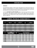
Страница 3: ...LO DIMENS ES A L P cm COMPRESSOR HP NOMINAL MASSA DO APARELHO G S HFC MASSA DO G S REFRIGERANTE EGC 75A EGC 150A 111 x 89 x 54 78 kg 2 x 1 3 R 134a 2 x 225 g MODEL DIMENSIONS A L P cm COMPRESSOR NOMIN...

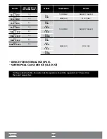
Страница 4: ...5 EGC 150MA 220V 2 5 MODEL COMPRESSOR MODEL EMBRACO FFI 12 HBX EGC 75A EGC 100A EGC 150A EGC 150MA TECUMSEH AE4430Y AE 540 EMBRACO FFI 8 5 HBK EGC 50A TECUMSEH AE4450Y AE 660 EGC 75A EGC 100A EGC 150A...

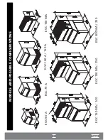
Страница 5: ...EGC 150 MA 140 EGC 150 MA 250 EGC 300 MA 250 MODELS AND POSSIBLE CONFIGURATIONS 4 EGC 75 A EGC 100 A 150 A EGC 150 MA EGC 50 A...

Страница 6: ...ling the equipment A Check if the place has drinking water B The equipment must be leveled C Check if the fan blades 24 turn freely D Make sure the voltage of the power supply network is in accordance...

Страница 7: ...try point Notes 1 Diagram for installer s guidance only 2 Items 2 and 3 of the installation diagram are not an integral part of the equipment 3 The buyer is responsible for installing the equipment 4...

Страница 8: ...s solenoid valve 28 Allows the hot coolant gas to enter the evaporator directly causing the ice to detach therefrom J Water solenoid valve 63 Its function is to fill the water trough at the beginning...

Страница 9: ...ary stop this action avoids the residual water which is close to zero degrees from reaching the tank thermostat 61 and switching off the Ice Machine unnecessarily 4 OPERATION OF THE TANK THERMOSTAT 8...

Страница 10: ...the stainless steel as well as ensuring the best quality of ice produced Before starting maintenance unplug the machine and remove the machine s cover 1 except for the EGC 150MA model For the EGC 150M...

Страница 11: ...E EGC 150A NAME OF MAIN COMPONENTS 1 2 3 4 5 6 7 8 9 10 11 12 13 14 15 16 17 18 19 20 21 22 24 23 25 26 27 28 29 30 31 32 33 35 37 34 36 38 40 41 42 43 44 45 46 47 48 49 50 51 52 53 54 55 56 57 58 59...

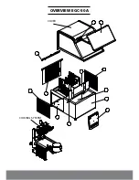
Страница 12: ...OVERVIEW EGC 50A COVER COOLING SYSTEM...

Страница 13: ...OVERVIEW EGC 75A EGC 100A AND EGC 150A In the EGC 150A model there are two compressors and two fans...

Страница 14: ...13 I OVERVIEW EGC 150MA I...

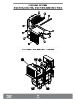
Страница 15: ...14 COOLING SYSTEM EGC 50A EGC 75A EGC 100A AND EGC 150A I COOLING SYSTEM EGC 150MA I...

Страница 16: ...ELECTRICAL ELECTRONIC PART...

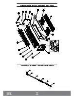
Страница 17: ...TROUGH DISPLACEMENT SYSTEM DISPLACEMENT ARM ASSEMBLY TROUGH...

Страница 18: ...LVE WATER LEVEL SENSOR RELAY START UP CAPACITOR START UP CAPACITOR FAN THERMAL PROTECTOR WATER LEVEL SENSOR MICRO GEAR MOTOR END OF CYCLE MICROSWITCH CIRCUIT BOARD REDUCER GAS VALVE WATER VALVE FAN MI...

Страница 19: ...Y START UP CAPACITOR PHASE PHASE THERMAL PROTECTOR PHASE THERMAL PROTECTOR PHASE START UP CAPACITOR RELAY MODEL AE 4450 Y THERMAL PROTECTOR CIRCUIT BOARD MICRO GEAR MOTOR END OF CYCLE MICROSWITCH REDU...

Страница 20: ...When there is an anomaly in this function it controls the main components gear motor 60 micro gear motor 57 gas solenoid valve 28 and water solenoid valve 63 in order to resolve the aforementioned an...

Страница 21: ...water then turns on the gear motor 60 taking the plastic trough 35 to the lowest position and discarding the little water that may have entered A by pass cycle starts and then the circuit board 62 sw...

Страница 22: ...nd the motor gearfor 10 minutes After this period it starts a new attempt at lowering 3 SYMPTOM TROUGH 35 IS LOWERED BUT DOES NOT REACH THE LOWEST POINT Probable causes Damage to the displacement syst...

Страница 23: ...astic lowering grating 4 blocking the passage of the plastic trough 35 reversible defect Lower Reed Switch 58 short circuited irreversible defect Displacement system spring 31 damaged irreversible def...

Страница 24: ...ion the plastic trough 35 descends to the lowest position and starts a by pass cycle to allow the ice cubes which are attached to the evaporator thimbles to detach themselves and fall into the ice tan...

Страница 25: ...NOT WORK PROBABLE CAUSES CORRECTION Tank thermostat 61 is at a very hot position or faulty Adjust or replace the tank thermostat 61 switched off 1 5 C to 4 C Faulty electrical plug Replace the electr...

Страница 26: ...ect and recharge with correct load Dirty condenser 25 Clean the condenser 25 Blocked air circulation Move the machine to an appropriate location Low water level in the plastic trough 35 Adjust the wat...

Страница 27: ...ormer 2 7 CUBES DO NOT DETACH FROM THE EVAPORATOR PROBABLE CAUSES CORRECTION Loss of refrigerant gas Check correct and recharge with correct load Gas solenoid valve 28 does not fully open red LED on C...

Страница 28: ...trough 35 using two oblong screws allowing the position to be moved up or down C B Lowest point The plastic trough 35 will be correctly stopped at the lowest point when touching the rear stop plates...

Страница 29: ...9 have two main purposes 1 To stir the water for improved efficiency of heat exchange with the cube makers in the evaporator 20 2 To control ice thickness To replace the finned axis 50 observe the fol...

Страница 30: ...cro gear motor 57 and see if it works freely If not check the alignment of the right 39 and left panel 44 of the cylinder head 34 and 44 the gap between the bronze bushing 32 any warping on the finned...

Страница 31: ...ure 3 is open If so remove it and before replacing it locate the controlled component that is shorted with the aid of an ohmmeter B There is voltage If there is voltage Before replacing the circuit bo...

Страница 32: ...h the pointer of the voltmeter on the terminal H of the circuit board 62 restart the equipment In up to 8 seconds it should indicate 220V If it does not replace the circuit board 62 Gear motor 60 As t...

Страница 33: ...voltage on the terminals A of the circuit board 62 replace the board If the water solenoid valve 63 does not switch off i e as if water was going straight into the plastic trough 35 switch off the eq...

Страница 34: ...lization to the atmospheric pressure with R 134a coolant Evacuation of the system up to 500 microns Hg These operations aim at obtaining the dilution of non condensable gases in the system so that the...

Страница 35: ...between 0 8 and 1 7kgf cm2 11 and 24 psig The low pressure at the end of the ice cycle is between 0 5 and 0 8 kg cm2 7 and 12 psig The low pressure during the defrosting cycle is between 0 5 and 0 8 k...

Страница 36: ...35...

Страница 37: ...36 EVEREST REFRIGERA O IND E COM LTDA RESERVES THE RIGHT TO MAKE CHANGES TO ITS EQUIPMENT WITHOUT PRIOR NOTICE...


Страница 38: ...assistance please have the machine model invoice and serial number at hand 0800 0240332 assistec everest ind br MANUFACTURER S TECHNICAL ASSISTANCE EVEREST REFRIGERA O IND STRIA COM RCIO LTDA Rua Card...

Отзывы: