


Alarms
7100A User Manual
5-4
5.3. LOAD MONITORING
Note:
•
Thermal faults are
signalled
by the ‘
T°
’ LED if one of the alarm options or one of the
control options (except V2 and OL) is fitted. The unit is
protected
against thermal faults
whether or not they are signalled.Thermal faults are signalled by the alarm relay
if
one of
the alarm options is fitted.
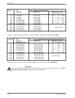
GRF
DLF
CHK
T
°
SET
Red LED:
"Over-temperature" (
≥
125 A)
Red LED:
"Serious faults"
Orange LED:
"Partial load failure"
DLF alarm adjustment
and diagnostic
push button
Figure 5-2 Layout of front panel LEDs with ‘GRF’ and/or ‘DLF’’ option
LED State
Firing
Typical
Fault
‘T°’
‘GRF’
‘DLF’
‘HEAT’
stopped
reaction
red
red
orange
green
time
Partial Load Failure
OFF
OFF
Flashing
(PLF)
ON
No 5 s to 13 s
Total Load Failure
OFF
ON
Flashing
or
(TLF)
Flashing
Thyristor Short-Circuit OFF
ON
OFF
(THSC)
Over-temperature (T°) ON
OFF
OFF
OFF
Yes
Table 5-1 LEDs for serious alarms or faults with ‘GRF’and/or ‘DLF’ options
Two diagnostic options are available :
• GRF option (Gross Fault) which permits to detect the following serious faults :
Total Load Failure : TLF
Thyristor Short-Circuit : THSC
Over Heating : T° (for units 250 A only)
• DLF option (Diagnostic Load Failure), presents the same fault detection as GRF option with in
addition, the Partial Load Failure detection (PLF).


