7100A User Manual
2-7
Installation
2.3. WIRING
2.3.1. POWER CONNECTIONS
Table 2-2a Power connection details for ratings from 16 A to 100 A
Rating
Terminal capacity
Torque
Stripping length
A
mm
2
AWG
Nm
mm
16 to 25
2.5 to 6
13 to 9
1.2
13
40 to 63
6 to 16
9 to 5
1.8
13
80 to 100
16 to 35
5 to 2
3.8
20
7100A power thyristor units with current ratings up to 100 A are fitted with:
• one channel controlled by thyristors
• an internal busbar for directly connecting the load to the power supply (direct channel, not
controlled by thyristors).
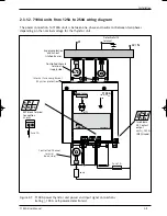
The wiring diagram for this range of standard current ratings is shown in figure 2-6.
The protective earth terminal
PE
(marked with the earth symbol) must be wired to the protective earth
(see section ‘Safety during installation’).
The 7100A units
≥
100 A, are equiped of : One thyristor controlled channel
The protective earth terminal
PE
(marked with the earth symbol) must be wired to the protective earth
(see section ‘Safety during installation’).
Use 75 °C min. copper wire only.
Conductor cross-sections should comply with IEC 60943.
Table 2-2b Power connection details for ratings from 125A to 250A
Rating
Terminal capacity
Torque
Stripping length
A
mm
2
AWG
Nm
mm
16,4 (or 28,8)
125 50 to 120
0
M10 nut
ø 10 (or ø 12)
160 70 to 120
00
to attach eyelet
200
95 to 120
000
and terminal
250
120
-
71A2_Installation_ENG_Iss3.qxp 1/09/06 16:14 Page 2-7

