Control / Limits
7100A User Manual
4-2
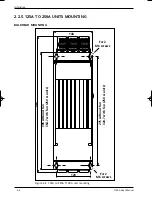
Figure 4-1 Ratio between control system input and output
The ratio between the setpoint and the control parameter (V
2
, I
2
or P) is
linear
.
Four types of input signal are available in the thyristor unit product codes:
0 - 20 mA or 4 - 20 mA, 0 - 5 V or 0 - 10 V.
100%
75
50
25
S
i
100 %
96%
Control
parameter
0 %
4%
U
2
, I
2
or P
Vrms or Irms
4. Chapter 4 CONTROL AND LIMITS
4.1. CONTROL
4.1.1. Control parameters
7100A power thyristor units use one of the following control parameters:
• rms load voltage squared
V
2
• rms load current squared
I
2
• power delivered to load
P
• Open Loop
OL
The parameters are defined and explained in the table below:
Control
Definition
Code
V2
Compensation of supply voltage variations
V2CL
Compensation of supply voltage variations with current limit
VICL
Power control with current and power limits
I2
Current squarred control
Only available with Phase Angle Mode (code PA)
OL
Open loop, no control. The output is the image of the setpoint
Only available with Phase Angle Mode (code PA)
Tableau 4-1 Control parameter use
For the Base version (with no options) the
standard
control parameter is V
2
.
The control parameter must be selected when ordering and forms part of the product code.
4.1.2. INPUT / OUTPUT RATIO
The value of the control
parameter
is
proportional
to the analogue setpoint signal between 4% and
96% of the scale (see figure 4-1).
71A4_Régulation_ENG_Iss2_1.qxp 1/09/06 16:15 Page 4-2

