


590 DRV Digital DC Drive Product Manual
App. M - 25
Appendix M Special Blocks and Application Notes
M
6. Check the tension loop performance by making step changes to the tension demand and moni-
toring the tension feedback. Increasing the proportional gain gives faster response but at some
point the winder will become unstable. If this occurs, reduce the gain until it regains stability.
The proportional gain is controlled by a profiler using PROP. GAIN, MIN PROFILE GAIN,
and MODE. The default for MODE is 0 causing PROFILED GAIN to equal PROP. GAIN. It
keeps the gain at PROP. GAIN throughout the diameter range. As a result, adjust PROP. GAIN
during initial tests at standstill with an empty core.
7. Once stable proportional control is achieved , set the INT. DEFEAT to OFF .
8. The integral action ensures a zero steady-state error at all line speeds. INT. TIME can be re-
duced to improve response; however, if the time is set too short, instability will occur.
9. Derivative action may be useful to increase the damping of the position loop; especially with
large rolls. Adjust DERIVATIVE TC as necessary. For loadcell tension control, DERIVATIVE
TC should not be required so leave it set to zero.
10. Start the line and increase the speed to about 10 percent of full speed. Monitor the tension con-
trol and adjust the tuning as required.
11. With the proportional gain optimized at core, record the PROP. GAIN value. Now it is neces-
sary to check the performance at full roll. Either run the line until a full roll is wound or, stop
the line and replace the empty core with a full roll and re-attach the web.
13. Before performing the stability tests with a full roll, the full roll diameter must be preset. Set
the input to terminal A2, EXTERNAL DIAMETER PRESET, to 10 volts for full roll diameter.
24 volts at terminal C7, PRESET ENABLE, sets the diameter to 100 percent. The diameter can
be monitored at SPECIAL BLOCKS:: DIAMETER CALC.:: DIAMETER.
14. At this point, PROP. GAIN probably needs to be increased to produce optimum performance at
full roll. If this is the case, adjust MIN PROFILE GAIN to give optimum performance through-
out the roll. MIN PROFILE GAIN should be reduced by the amount the PROP. GAIN was in-
creased as shown in the equation below.
MIN PROFILE GAIN
NEW
= (PROP. GAIN
OLD
/ PROP. GAIN
NEW
) * 100%
For example, if the PROP. GAIN at core was 10 percent and it was increased to 20 percent at
full roll, reduce MIN PROFILE GAIN from the default 100 percent to 50 percent.
15. MODE allows the change of proportional gain with diameter to be varied. The winder perfor-
mance should be monitored throughout the buildup of the roll at various line speeds. MODE
would be changed so the proportional gain at each diameter fits the required gain profile better.
The higher the setting for MODE, the lower the gain at smaller diameters.
16. Save parameters
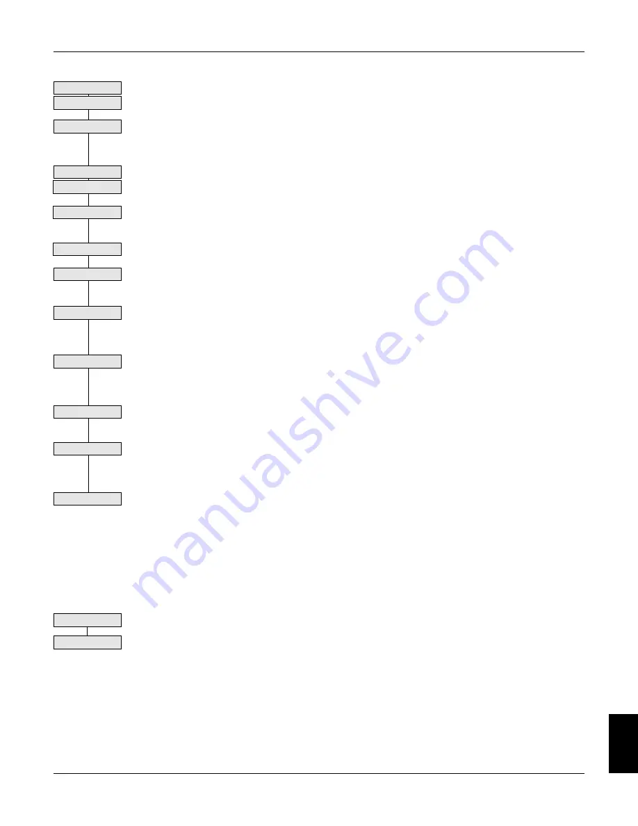
Check tension loop
Continued
Adj. Prop. Gain
Record Prop. Gain
Start line to 10%
Adj. Derivative
Adj. Int. Time Const.
Int. Defeat OFF
Preset full roll dia.
Incr Profile Gain
New Min Pro Gain
Save Parameters
Adjust Mode
Winders with Dancer Feedback
The start-up procedure using dancer feedback is the same as for loadcell feedback except for the following changes:
Unwinds
Follow the same procedure used for rewinds except as follows.
Speed Mode
2a. Set O/P SCALER(TRIM) to -10 percent. This sets the correct loop polarity so that the loadcell
or dancer feedback remain unchanged.
2b. Set terminal C7, PRESET ENABLE, to ON. Initially, set terminal A2, EXTERNAL DIAM-
ETER PRESET to to core.
Tension mode
An unwind cannot run at any speed with an empty core. As a result, after completing the test at standstill with an
empty core, step 8, skip directly to full roll tests, step 13.
Set O/P Scaler
Set preset to core
Содержание 590 DRV Digital
Страница 2: ......
Страница 16: ...1 4 Chapter 1 Introduction 1 590 DRV Digital DC Drive Product Manual ...
Страница 22: ...2 6 2 Chapter 2 Identification 590 DRV Digital DC Drive Product Manual ...
Страница 45: ...Figure 3 20 Wiring Circuit Diagram for 590 DRV Digital Drive ...
Страница 77: ...5 22 5 590 DRV Digital DC Drive Product Manual Chapter 5 Troubleshooting ...
Страница 103: ...App A 18 A Appendix A Technical Description 590 DRV Digital DC Drive Product Manual ...
Страница 107: ...B Appendix B Using the Man Machine Interface App B 4 590 DRV Digital DC Drive Product Manual ...
Страница 114: ...Appendix C Setup Parameters 590 DRV Digital DC Drive Product Manual App C 7 C Figure C 8 Aux I O ...
Страница 120: ...Appendix C Setup Parameters 590 DRV Digital DC Drive Product Manual App C 13 C t Figure C 13 Field Control ...
Страница 122: ...Appendix C Setup Parameters 590 DRV Digital DC Drive Product Manual App C 15 C Figure C 14 Field Current Variables ...
Страница 124: ...Appendix C Setup Parameters 590 DRV Digital DC Drive Product Manual App C 17 C Figure C 15 Field Weakening Variables ...
Страница 126: ...Appendix C Setup Parameters 590 DRV Digital DC Drive Product Manual App C 19 C Figure C 16 Current Profile ...
Страница 128: ...Appendix C Setup Parameters 590 DRV Digital DC Drive Product Manual App C 21 C t t t Figure C 17 Stop Rates ...
Страница 134: ...Appendix C Setup Parameters 590 DRV Digital DC Drive Product Manual App C 27 C Figure C 22 Setpoint Sum ...
Страница 138: ...Appendix C Setup Parameters 590 DRV Digital DC Drive Product Manual App C 31 C Figure C 25 Speed Loop ...
Страница 142: ...Appendix C Setup Parameters 590 DRV Digital DC Drive Product Manual App C 35 C Figure C 27 Speed Loop Setpoints ...
Страница 144: ...Appendix C Setup Parameters 590 DRV Digital DC Drive Product Manual App C 37 C Figure C 28 Current Loop ...
Страница 146: ...Appendix C Setup Parameters 590 DRV Digital DC Drive Product Manual App C 39 C Figure C 29 Inhibit Alarms ...
Страница 148: ...Appendix C Setup Parameters 590 DRV Digital DC Drive Product Manual App C 41 C Figure C 30 Calibration t ...
Страница 149: ...Appendix C Setup Parameters 590 DRV Digital DC Drive Product Manual App C 42 C ...
Страница 169: ...Appendix D I O Configuration System Menu App D 20 D 590 DRV Digital DC Drive Product Manual Figure D 17 Block Diagram ...
Страница 173: ...Appendix D I O Configuration System Menu App D 24 D 590 DRV Digital DC Drive Product Manual ...
Страница 174: ...Figure D 20 590 DRV Digital DC Drive Software Block Diagram t t t t ...
Страница 202: ...App F 18 Appendix F Spare Parts List 590 DRV Digital DC Drive Product Manual F ...
Страница 208: ...Appendix G RS232 System Port P3 590 DRV Digital DC Drive Product Manual App G 6 G ...
Страница 234: ...Appendix H RS422 Communications Ports P1 P2 590 DRV Digital DC Drive Product Manual App H 26 H ...
Страница 250: ...Appendix J Parameter List by Menu App J 8 J 590 DRV Digital DC Drive Product Manual ...
Страница 258: ...Appendix K Parameter List by Parameter Name 590 DRV Digtial DC Drive Product Manual App K 8 K ...
Страница 318: ...590 DRV Digital DC Drive Product Manual App M 38 Appendix M Special Blocks and Application Notes M ...


