background image

EK-MFR/1                              Arch.2573


Rev. E  of  22/06/2007 

       Sh. 28 of  35 


                               501-000658/MN  


Eurotek s.r.l.


8.1 

EK-MFR/1 web pages 

 
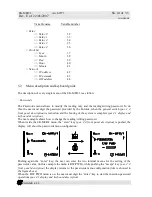
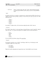
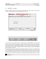
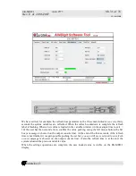
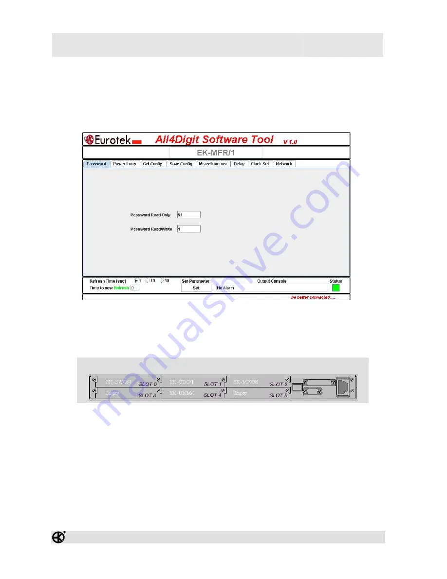
When the All4Digit Software Tool is running, the EK-MFR/1 web page is automatically loaded on 
the screen of the terminal unit and the following image is showed. 


The  page  shows,  in  the  central  section,  the  complete  menu  of  the  EK-MFR/1  unit  (board  menu 
chapter
). The selected menu is in light colour and its variables are reported in the centre of the page. 
The  other  menu  that,  are  not  temporarily  selected,  are  visible  in  dark  colour.  In  the  figure,  the 
Password menu is active and the read only and read write password value are reported on the screen. 
In  the  top  section  of  the  page  is  reported  the  name  of  the  selected  unit  (in  this  case  EK-MFR/1) 
under the software tool name. 
The down side of the page is featured by the following parameter: the refresh time variable allows 
to  set  the  useful  time  to  confirm  the  setting  of  a  menu  variable.  The  time  to  new  refresh  window 
gives information about the countdown of the refresh time. The Set parameter box allows to confirm 
the  setting  of  a  menu  variable.  The  output  console  line  with the  status  square  are  used  to  obtain  a 
view of the alarm conditions of the entire system. During the normal working conditions, the output 

Содержание EK-MFR/1

Страница 1: ...EK MFR 1 Arch 2573 Rev E of 22 06 2007 Sh 1 of 35 501 000658 MN Eurotek s r l User s handbook Digital radio Link EK MFR 1 ...

Страница 2: ...f the FCC Rules that fixed and guarantee the reasonable protection against such interference when it is used in a commercial environment When this equipment is installed in a residential area it could cause interference in which case the user must provide itself to avoid the interference The test results show compliance with the Class A limits for radiated emissions The present design is property ...

Страница 3: ...n contrast with enforced laws LIFE SUPPORT APPLICATIONS Eurotek s products are not designed for use as critical components in life support devices or system without the express written approval of the Eurotek S r l As used herein Life support devices or system are devices or system which a are intended for surgical implant into the body or b support or sustain life and whose failure to perform whe...

Страница 4: ...gum dental prosthesis etc otherwise set him free from foreign bodies Kneel near the patient s head and putting a hand under his neck incline as possible his her head backwards 3 Going on with keeping the patient s head inclined with one hand use the other one to occlude the nostrils if you are going to practise the breathing through the oral cavity or occlude the mouth if you want to do it through...

Страница 5: ...ESENTATION 13 5 2 MENU DESCRIPTION AND KEYBOARD GUIDE 14 5 3 TEMPERATURE CONTROL 19 6 LEDS AND ALARMS 19 6 1 LEDS DESCRIPTION 19 6 2 ALARMS DESCRIPTION 19 7 ABOUT OPERATING SYSTEM 20 7 1 OPERATING SYSTEM CONNECTION 20 7 2 OPERATING SYSTEM COMMANDS 20 7 2 1 Read_log 20 7 2 2 Erase_log 21 7 2 3 Passwd 21 7 2 4 Exit 22 7 3 OPERATING SYSTEM SNMP COMMANDS 22 7 3 1 Snmpwalk 23 7 3 2 Snmpset 24 7 3 3 Snm...

Страница 6: ...ped The setting operation of every single board can be done locally on the keyboard or by remote sites thanks to the placement of Ethernet 10 100 Base T interface located in the power supply section EK PWS X Inside the EK MFR 1 a re configurable connection lines are inserted matrix they allow the connection among all the slots inserted in the system leading therefore to an interconnection of the s...

Страница 7: ...EK MFR 1 Arch 2573 Rev E of 22 06 2007 Sh 7 of 35 501 000658 MN Eurotek s r l 1 1 EK MFR 1 block scheme ...

Страница 8: ...4 Display and Keyboard C Keyboard chapter 4 Display and Keyboard D Enter key E Green LED ON for power on indication chapter 6 LEDs and ALARMS F Red LED ACTUAL for alarm indication chapter 6 LEDs and ALARMS G Yellow LED STORED for alarms stored indication chapter 6 LEDs and ALARMS H Monitory connector I Escape key L Modifying variable keys M Explorer menu and display mode keys ...

Страница 9: ...ear panel view 3 2 Rear panel description A Slot 0 B Slot 1 C Slot 2 D EK PWS X panel E Slot 5 F Slot 4 here it is possible to install the modem EK UNM 1 G Slot 3 here it is possible to install the coaxial adapter EK CDP 1 The different power supplies solutions are descibed in the EK PWS X manual ...

Страница 10: ...a special password of five number must be inserted The procedure for the insertion of the password is explained below Press the modifying variable keys par 2 2 front panel description to visualize the number from 0 to 9 Choose the first value to insert and confirm it with the enter key Insert the second value confirm it and repeat the procedure until the last number If an error occurs the user mus...

Страница 11: ...ription it is possible to see on the display the boards that the EK MFR 1 contains and the relative slot associated to the board The example below shows the EK UNM 1 board that is inserted in the slot number 4 Pushing the enter key it is possible to enter in the selected board menu The RW letters appear in the figure above near the key symbol this indicates that the actual active password allows t...

Страница 12: ... on the display that moreover supplies the output interface of the EK MFR 1 processor Every slot has the interconnections for two video signals that can be showed on the TFT colour monitor if the board is enabled for this function There are three different modalities either only the text is showed or the text and the video are showed or only the video is showed Every different modality can be sett...

Страница 13: ... r w PWD 3 Power Loops Loop 1 Enable 1 4 Source 1 5 Target 1 6 P Goal 1 7 P Source 1 8 Loop 2 Enable 2 9 Source 2 10 Target 2 11 P Goal 2 12 P Source 2 13 Loop 3 Enable 3 14 Source 3 15 Target 3 16 P Goal 3 17 P Source 3 18 Get Config Get from 19 Save Config Save to 20 Miscellaneous Volt in 0 21 Volt in 1 22 Volt out 0 23 Volt out 1 24 Board Temp 25 12V rail 26 3 3V rail 27 DC rail in 28 Time to e...

Страница 14: ...2 2 front panel description is turned on and the booting of the system is complete par 4 1 display and keyboard description The next example shows how to change the reading writing password When inside the EK MFR 1 menu the enter key par 2 2 front panel description is pushed the display will show the passwords menu configuration Pushing again the enter key the user can enter the two internal menus...

Страница 15: ...ps are therefore in a position to adjust three different transmitters connected to the same EK MFR 1 to simplify the process we are analyzing the relative function to LOOP1 which is identical to the other two The Loop 1 menu is composed by five sub menus Enable 1 Source 1 Target 1 P Goal 1 P Source 1 BLOCK SCHEME OF THE POWER LOOP SYSTEM In the sub menu SOURCE we define in which slot of the EK MFR...

Страница 16: ...er Loops supposing of working with the QPSK modulations to obtain a back off of 4 db relating the saturate power 0 db of the transmitter SHF connected to EK MFR 1 by the EK CDP 1 board 1 Source1 slot3 indicates where reading the saturate power 2 Target1 slot4 indicates where setting the IF power level in order to obtain the back off planned EK UNM 1 3 P Goal1 4db indicates the back off level to be...

Страница 17: ...ually present on the pin 17 of the auxiliary connector of the EK PWS X board Volt out 0 Allows to set a DC voltage 0 12 VDC 10 mA max at the output of the auxiliary connector pin 5 of the EK PWS X board Volt out 1 Allows to set a DC voltage 0 12 VDC 10 mA max at the output of the auxiliary connector pin 18 of the EK PWS X board Board Temp Allows to read the EK PWS X board temperature 12V rail Allo...

Страница 18: ...Relay 0 Relay 1 Relay 2 Relay 3 Relay 4 Every Relay is enabled with the ON function and disabled with the OFF function Clock Set The Clock Set menu allows to set the parameters of the internal time system Through the explorer menu keys par 2 2 front panel description it is possible to set the five sub menus below Year Month Day Hour Minute It is not available the automatic setting of the summer ti...

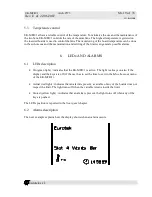
Страница 19: ...ible alarms 6 LEDs AND ALARMS 6 1 LEDs description On green light indicates that the EK MFR 1 is active The light is always on also if the display and the keys are off if the user has to set the time to exit in the Miscellaneous menu of the EK MFR 1 Actual red light indicates that an alarm is present a variable of any of the boards does not respect the limit The light turns off when the variable r...

Страница 20: ... of the connectors with the pins indication is reported in the EK PWS X user s handbook When the EK MFR 1 is connected and the general switch is turned on par 2 2 front panel description the insertion of the EK MFR 1 login is required EK MFR 1 login The user must enter in the system using the super_user login and digits it as follow after the insertion of the login is necessary to push the return ...

Страница 21: ...e alarm is stopped The variable value 7 2 2 Erase_log The erase_log command allows to erase the log file When the command is launched the below view is showed on the screen of the terminal unit erase_log M25P80 1024KB SPI flash found Log event bulk erase log_event_erase OK No item found log_add_event pbuf 0 log_add_event write Log erased page_program return 40 The first line of the new log file af...

Страница 22: ...er new password qwe123r Re enter new password qwe123r Password changed The qwe123r combination is an example of available password the re insertion value operation is required and then the password is changed 7 2 4 Exit The exit command is used to exit from the super_user login When the command is executed the user is disconnected from the system exit The following message appears when the user is...

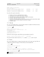
Страница 23: ...ed the return key the user can see the following view SNMPv2 SMI enterprises 19222 1 6 1 0 STRING Slot4 EK UNM 1 SNMPv2 SMI enterprises 19222 1 6 2 0 STRING 10 5 SNMPv2 SMI enterprises 19222 1 6 3 0 STRING 29 0 SNMPv2 SMI enterprises 19222 1 6 4 0 STRING 3 4 SNMPv2 SMI enterprises 19222 1 6 5 0 STRING 16QAM SNMPv2 SMI enterprises 19222 1 6 6 0 STRING 0 35 SNMPv2 SMI enterprises 19222 1 6 7 0 STRIN...

Страница 24: ...ixed string slot 2 the number of the slot plus 2 with the variable to set For example to set a variable value of the slot number 4 the label slot 2 will be set to the 6 value variable number the number of the variable to set s fixed label variable value the value of the variable to set We suppose to set the read write password value chapter 5 board menu password of the EK MFR 1 to the 7 value The ...

Страница 25: ...n variable is 5 EK UNM 1 user s handbook chapter 5 board menu so the command to digit will be snmpget v1 c public 192 168 1 7 1 3 6 1 4 1 19222 1 6 5 When the command is launched the screen of the terminal unit returns this message SNMPv2 SMI enterprises 19222 1 1 6 3 STRING 16QAM 8 WEB INTERFACE The EK MFR 1 system supplies a web interface software tool All4Digit Software Tool that allows to obta...

Страница 26: ...stem it is necessary to insert a user name and a password The user name available for the user is super_user The password value is pollon When the user name and the password values are inserted pushing on the OK window it is possible to enter in the EK MFR 1 main web page like the next image shows ...

Страница 27: ...unit rear panel description paragraph with the board that are inserted in the system Using a mouse it is possible to move the cursor on the rear panel To examine the content of any board it is necessary to move the cursor on the board name and to click the left mouse button to enter in the board menu In the centre of the page is reported the web page of the EK MFR 1 explained in the next paragraph...

Страница 28: ...In the figure the Password menu is active and the read only and read write password value are reported on the screen In the top section of the page is reported the name of the selected unit in this case EK MFR 1 under the software tool name The down side of the page is featured by the following parameter the refresh time variable allows to set the useful time to confirm the setting of a menu varia...

Страница 29: ...e of the board became red The next example explains how to set a parameter of the EK MFR 1 menu We suppose to change the value of the time to exit parameter for the system the procedure to set this variable is similar for the other parameter of the EK MFR 1 unit The time to exit parameter is located in the Miscellaneous menu board menu chapter so when this menu is selected the next web page appear...

Страница 30: ...EK MFR 1 Arch 2573 Rev E of 22 06 2007 Sh 30 of 35 501 000658 MN Eurotek s r l We suppose to choose the 10 minute value for the Time to Exit variable so the screen shows ...

Страница 31: ...ple time to exit 10 the user has then seconds for to confirm the value pushing using the left mouse button the Set box a message is showed on the output console line At the end of the then seconds if the refresh time is not finished it is again possible pushing the set box you can still press set until new refresh occurs message is showed on the output console line if also the refresh time is at t...

Страница 32: ...Audio out GND EARTH Common Video pal out 12 GND EARTH GND EARTH GND EARTH 13 5V 5V 5V 14 NOT CONNECTED NOT CONNECTED NOT CONNECTED 15 QSPI_BOARD_EN in QSPI_DIN in HIGH_SPEED_DATA0 16 QSPI_DOUT out QSPI_CLK in HIGH_SPEED_DATA1 17 IRQ_REQ out RESET HIGH_SPEED_DATA2 18 NOT CONNECTED HIGH_SPEED_WE HIGH_SPEED_DATA3 19 10 MHz REF HIGH_SPEED_OE HIGH_SPEED_DATA4 20 3V3 GND EARTH HIGH_SPEED_DATA5 21 NOT CO...

Страница 33: ...addresses Addresses Bus Range CS 0x00000000 0x003FFFFF CS0 Flash Boot 4 MByte 0x30000000 0x3FFFFFFF CS1 FPGA CSFPGA_0 0x30000000 0x3000001F Matrix 0x30000360 0x3000037F Keyboard 0x20000000 0x203FFFFF CS7 SDRAM 16 Mbyte 0x10000000 0x1FFFFFFF MBAR Module Base Address Register QSPI BUS CS 0 1 2 3 4 Slot 0 5 PWS 0 Relay SCI enable on PWS 6 6 PWS 1 AD DA converter on PWS 6 7 Serial EEprom 8 On Screen D...

Страница 34: ...e 2 Flash seriale configurazione FPGA 3 Richiesta Slave 4 Reset Slot 5 6 PPP protocol EK UNM 1 board 7 8 9 A B C D E F APPENDIX C RS232 interface settings To connect the EK MFR 1 to a terminal unit by the RS232 interface is necessary to set the following value of the COM port parameter 115200 bauds 8 data bits NO parity bit 1 STOP bit NO flow control ...

Страница 35: ...0658 MN Eurotek s r l Eurotek S r l c o Parco Scientifico Tecnologico e delle Telecomunicazioni in Valle Scrivia Strada Comunale Savonesa 9 15050 RIVALTA SCRIVIA AL tel 39 0 131 860205 r a fax 39 0 131 860993 http www eurotektel com e mail info eurotektel com ...

Отзывы: