EK-MFR/1 Arch.2573
Rev. E of 22/06/2007
Sh. 15 of 35
501-000658/MN
Eurotek s.r.l.
>Power loops
The Power Loops menu allows to control automatically the output level of one board inserted in a
slot in according to the output level of a board inserted in another slot of the EK-MFR/1. This
functionality it used in order to keep constant the output power of a transmitter to adjusting the
modulator output power.
The three loops are therefore in a position to adjust three different transmitters connected to the
same EK-MFR/1; to simplify the process we are analyzing the relative function to LOOP1, which is
identical to the other two. The Loop 1 menu is composed by five sub-menus: Enable 1, Source 1,
Target 1, P Goal 1, P Source 1.
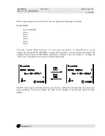
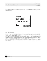
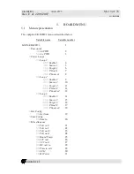
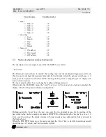
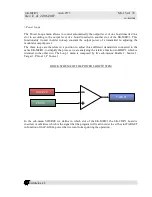
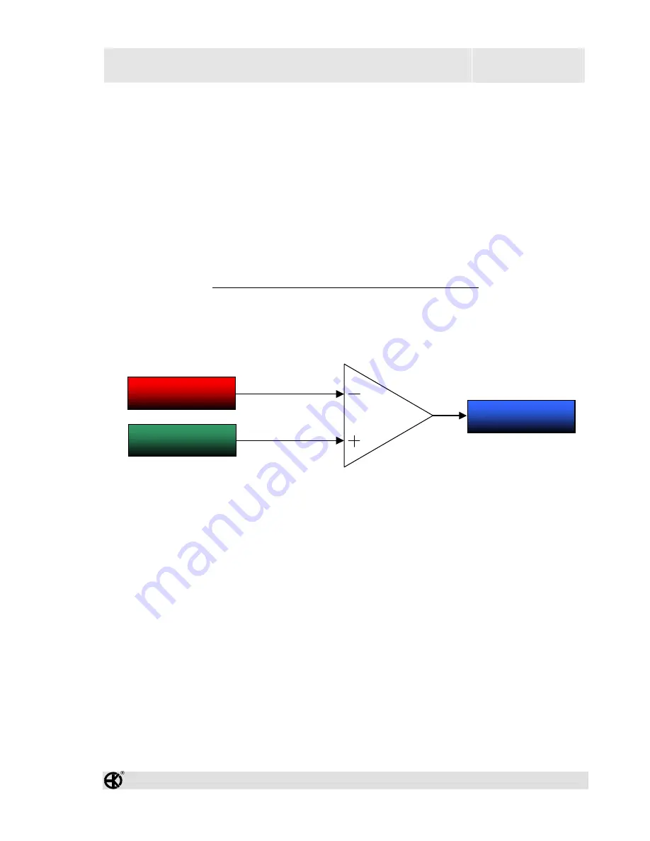
BLOCK SCHEME OF THE POWER LOOP SYSTEM
In the sub-menu SOURCE we define in which slot of the EK-MFR/1 the EK-CDP/1 board is
inserted, or otherwise which is the signal that the program will read in order to set the slot TARGET
in function of the P-GOAL power that we want to keep during the operation.
SOURCE
P GOAL
TARGET


