Hub van Doorneweg 8 • 2171 KZ Sassenheim – NL •
T
+31(0)252 228850 •
F
+31(0)252 228235 •
E
I
euronormdrives.com
Hub van Doorneweg 8 • 2171 KZ Sassenheim – NL •
T
+31(0)252 228850 •
F
+31(0)252 228235 •
E
I
euronormdrives.com
22
23
NEURN030000_220_A
NEURN030000_220_A
6.3.2 .Function description of main circuit terminal
Terminal
Name
Explain
R
Inverter input terminals
Connect to three-phase power supply,
single-phase connects to R, T
S
T
Chapter 4 Installation and commissioning
42
Cha
pt
er 4
/PE
Ground terminals
Connect to ground
+, RB
Braking resistor
terminals
Connect to braking resistor
U
Output terminals
Connect to three-phase motor(Please do not connect
single phase motor)
V
W
+, -
DC bus output terminals
Connect to braking unit
P, +
DC reactor terminals
Connect to DC reactor(Remove the shorting block)
4-3-3.
Varistor and
safety
capacitor switch
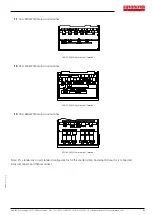
For the power grid system with neutral grounding, the customer needs to close the varistor
switch (VDR) and safety capacitor switch (EMC) by himself (i.e. press the switch "1");
If it is used in it power grid system (neutral point to ground insulation or high impedance
grounding), the varistor (VDR) to ground switch and the safety capacitor (EMC) to ground switch
need to be disconnected, as shown in the figure below ("0" press down state is off state), and the
filter cannot be installed, otherwise the inverter may be damaged.
In the case of configuration of residual current circuit breaker, if leakage protection occurs
during starting, the safety capacitor (EMC) ground switch can be disconnected, as shown in the
figure below.
Varistor switch
Safety regulation capacitor switch
Figure 4-17
:
Schematic diagram of varistor switch (VDR) and safety capacitor switch (EMC)
/ PE
Ground terminals
Connect to ground
+, RB
Braking resistor terminals
Connect to braking resistor
U
Output terminals
Connect to three-phase motor
(Please do not connect single phase motor)
V
W
+, -
DC bus output terminals
Connect to braking unit
P, +
DC reactor terminals
Connect to DC reactor(Remove the shorting block)
6.3.3 Varistor and
safety
capacitor switch
For the power grid system with neutral grounding, the customer needs to close the varistor switch (VDR) and safety
capacitor switch (EMC) by himself (i.e. press the switch “1”);
If it is used in it power grid system (neutral point to ground insulation or high impedance grounding), the varistor (VDR) to
ground switch and the safety capacitor (EMC) to ground switch need to be disconnected, as shown in the figure below
(“0” press down state is off state), and the filter cannot be installed, otherwise the inverter may be damaged.
In the case of configuration of residual current circuit breaker, if leakage protection occurs during starting, the safety
capacitor (EMC) ground switch can be disconnected, as shown in the figure below.
Varistor switch
Safety regulation capacitor switch
Schematic diagram of varistor switch (VDR) and safety capacitor switch (EMC)
Содержание JI500
Страница 1: ...www euronormdrives com info euronorm nl 31 0 252 228850 Frequency Drive JI500 Manual...
Страница 99: ...99 NEURN030000_220_A...
Страница 100: ......
Страница 101: ...www euronormdrives com Hub van Doorneweg 8 Sassenheim...


