


Operating Instructions
Non-Contact Safety Switch CES-I-AR-.-C04-…
22
(translation of the original operating instructions) 2119563-08-07/17
10. Setup
10.1. LED displays
You will find a detailed description of the signal functions in chapter
11. System status table CES-I-AR-… on page 24
.
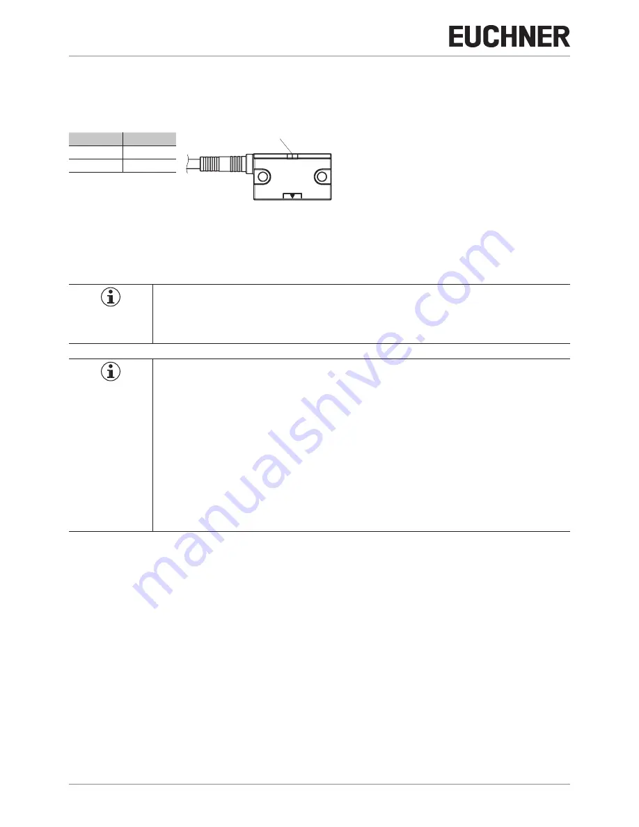
LED
Color
STATE
green
DIA
red
10.2. Teach-in function for actuator (only for unicode evaluation)
The actuator must be allocated to the safety switch using a teach-in function before the system forms a functional unit.
During a teach-in operation, the safety outputs and the monitoring output OD are switched off, i.e. the system is in the safe
state.
Tip!
It is recommended to perform the teach-in operation prior to mounting. Mark switches and actuators
that belong together in order to avoid confusion. For devices to be connected in series, we recommend
performing the teach-in operation separately for each device prior to series connection.
Important!
Ì
The teach-in operation may be performed only if the device functions flawlessly. The red DIA LED
must not be illuminated.
Ì
The safety switch disables the code of the previous actuator if teach-in is carried out for a new
actuator. Teach-in is not possible again immediately for this actuator if a new teach-in operation is
carried out. The disabled code is released again in the safety switch only after a third code has
been taught.
Ì
The safety switch can be operated only with the last actuator taught.
Ì
The number of teach-in operations is unlimited.
Ì
If the switch detects the actuator that was most recently taught when in teach-in standby state,
this state is ended immediately and the switch changes to normal state.
Ì
If the actuator to be taught in is within the operating distance for less than 60 s, it will not be acti-
vated and the most recently taught in actuator will remain saved.
10.2.1. Preparing device for the teach-in operation and teaching in actuator
1. Apply operating voltage to the safety switch.
¨
The green LED flashes quickly (approx. 5 Hz)
A self-test is performed during this time (approx. 8 s). After this, the LED flashes cyclically three times and signals that
it is in standby state for teach-in.
Standby state for teach-in remains active for approx. 3 minutes.
2. Move new actuator to the read head (observe distance < S
ao
).
¨
Teach-in operation starts, green LED flashes (approx. 1 Hz). During teach-in, the safety switch checks whether the actuator
is a disabled actuator. If this is not the case, the teach-in operation is completed after approx. 60 seconds, the green
LED goes out. The new code has been saved, the old code disabled.
3. To activate the new actuator code from the teach-in operation in the safety switch, the operating voltage to the safety
switch must then be switched off for min. 3 seconds.
LEDs