background image


www.electrotechsystems.com

    833-ESD-GURU  (833-373-4878) 

D00219 Revision E 

– 2019-07-19  - Page 32  


APPENDIX B 

– COM Port Setup 


The PinScan system uses three USB/COM ports to control the electronics.  PinScan and its laptop 
computer are shipped with the COM ports set properly so no attention from the user is necessary.  If the 
software is set up on a different computer or if there is any conflict with the COM port numbers, follow the 
steps in this section. 


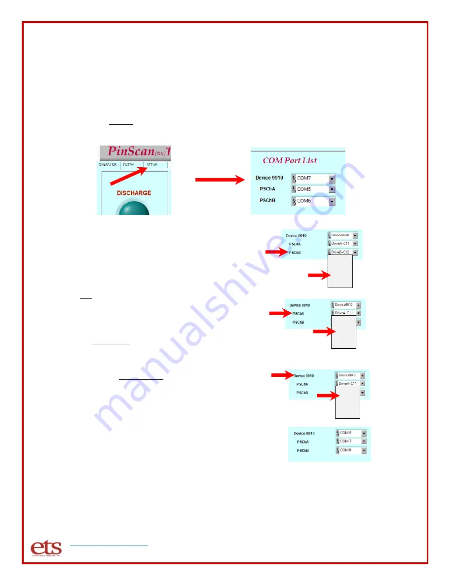
Find the SETUP tab above the Discharge indicator and click on it.   You will see 3 items listed, 
each with a pull-down menu.   These are the 3 communication channels used by PinScan.   


Pull down the menu for PSChB and you will see 

windows’ list of available com ports

 as shown at 

right.  Click on the last entry “Refresh” to update 

the list. 


Click on the PSChB menu again and click on the 
last 

“COM” entry on the list.  In the example at 

right, select COM8.  This assigns COM8 to 
PSChB.   


Now pull down the menu for PSChA and click on 
the next-to-last COM entry.  This assigns COM7 
to PSChA in our example.   


Now pull down the menu for Device 9910 and 
click on the 3rd-from-last COM entry.  This 
assigns COM6 to Device 9910 in the example.  
You should finish with the PinScan COM port 
list identical to the last 3 COM items appearing 
on the pull-down menus. 


Pull down any one of the menus and click on the 
Refresh entry. 


If the “Green light” indicator test during test 

preparation showed Red ON and Green OFF, 
swap the ports for PSChA and PSChB.  In this 
example that would assign COM8 to PSChA and 
COM7 to PSChB. 


COM5    

COM6 
COM7 

COM8 

Refresh 

COM5    

COM6 

COM7 
COM8 

Refresh 

COM5    

COM6 
COM7 

COM8 

Refresh 

Содержание PinPulse 9910

Страница 1: ...www electrotechsystems com 833 ESD GURU 833 373 4878 D00219 Revision E 20190722 ESD Testing System Model 9910 PinPulse PinScan Operating Manual...

Страница 2: ...TEST 12 4 9 MONITORING THE TEST 12 4 10 Viewing a Completed Test 14 V OPERATION GUIDE 16 5 1 Organization of the System 16 5 2 PinPulse 16 5 3 The Adapter Board 16 5 4 The PinMap 18 5 5 The PinScript...

Страница 3: ...ion Do not disable or remove the grounding pin If the outlet to be used does not accommodate the 3 prong plug either change the outlet or use a grounding adapter FUSES The system has no replaceable fu...

Страница 4: ...ons DO NOT OPERATE IN AN EXPLOSIVE ATMOSPHERE Operating the equipment in the presence of flammable gases powders or fumes CONSTITUTES A DEFINITE SAFETY HAZARD For equipment designed to operate in such...

Страница 5: ...and the necessary PinScan Test Manager software loaded and operational The PC has a standard AC 100 240 VAC power supply with power cord 3 Cabling kit includes 1 Two standard US power cables 2 a USB...

Страница 6: ...ts the 9910 lower electronics to the computer The other cable is a USB Type A to USB Type A cable which connects the PinScan transport upper electronics to the computer IMPORTANT Switch the PinPulse r...

Страница 7: ...rve trace cables The Red Black twisted pair of cables with smaller pin plugs connects to the small red and black jacks on the PinPulse connection panel Attach the black wire to the black Ground pin ja...

Страница 8: ...Program Control The Test Manager will indicate the running condition by the appearance of a black arrow at the upper left The program may be stopped using the red button or paused using the icon If th...

Страница 9: ...he PinScan Test Manager the yellow banner will display PinScan System READY indicating that PinScan is in the Ready Mode The system is controlled by the buttons across the top of the window The first...

Страница 10: ...e alignment is complete PinScan will ask you to click on GO to start the test PinScan always loads the most recent test and its PinScript Voltage Script and PinMap as a starting point For this quick s...

Страница 11: ...age Script loaded and ready to run and its number will appear in the VScript Ref field 7001 as shown in the example above Click on GO to accept this Voltage script 4 4 ENTER THE TEST AND DEVICE DESCRI...

Страница 12: ...nPulse 9910 will display on its front panel the first Voltage in the Voltage Script and the system will perform a discharge at this Voltage The after discharge Curve Trace will be performed PinScan wi...

Страница 13: ...cteristic is shown at the right An index number which we call PinCheck is computed for each curve trace PinCheck is a sensitive indicator of any change in the waveform If the PinCheck number remains n...

Страница 14: ...the list This chart is updated live when the testing order is Stepping by voltages If the order is Stepping by pins then this chart is completed at the end of the test 4 10 Viewing a Completed Test Cl...

Страница 15: ...urve traces and Next Pin and Prev Pin for navigation by device pin Click on Next CT to step to the next curve trace Click on Prev CT to step back to the previous curve trace Click on Next Pin to step...

Страница 16: ...he two requested pins then the Test Manager instructs PinPulse to create the required discharge 5 3 The Adapter Board At the right of the diagram is the user s Device with its own unique package shape...

Страница 17: ...64 pin Adapter board and two simple 3 lead components are mounted on it Adapter boards can be configured to handle a single large device or multiple smaller components with a total of up to 128 leads...

Страница 18: ...and down To change the script simply use the mouse cursor and keyboard to edit the pin numbers New steps can be added to the test by adding the pin numbers at the end of the list You will see the leng...

Страница 19: ...l accept Voltage numbers up to 8000 however anything outside the stated range for the present model MM 1 000V and HMM 5 000V will be limited to the maximum for the range On the Script Entry screen the...

Страница 20: ...ns a list of numbers representing voltages to be applied during the test Voltage TAB Voltage TAB Voltage TAB Voltage TAB Voltage RETN Example ETS9910VS TAB 5 TAB Low voltage sweep 50 90 RETN 50 TAB 60...

Страница 21: ...redictor of condition of the circuit Any damage to the part is likely to change the curve as shown in the two smaller plots Curve trace can be disabled by selecting No Curve Trace providing somewhat f...

Страница 22: ...an innovative feature which saves time by automating the comparison process Each time a curve trace is performed a characterization number the PinCheck number is generated based on the shape of the c...

Страница 23: ...hows the number of the Test pin and the Return pin and the mean and variance computed for all of the discharges applied to the pin pair One line is present for each step of the PinScript The results a...

Страница 24: ...txt xxxx denotes the PinScript number The Voltage Script file if changed ETS9910VSxxxx txt xxxx denotes the VScript number The PinScan Setup file ETS9910Setup txt Each test run also updates the setup...

Страница 25: ...length and description Each Log entry includes 1 Record identification ETS9910Log 2 The PinScript step number 3 The device test pin 4 The device return pin 5 The Voltage Script step number 6 The disc...

Страница 26: ...the pin pair As discharges are applied to a pin pair if the PinCheck number remains constant then a failure is unlikely Statistics are computed and when testing of a pin is complete the variance of al...

Страница 27: ...quency current measurement of the discharge The system includes a precision current probe the universally approved CT 1 sensor Viewing the discharge waveform requires a 1GHz or higher oscilloscope pro...

Страница 28: ...d up PinPulse should display status and PinScan should illuminate both the red and the green LEDs on its front panel as shown below If any deviation from this power down and re start If the problem pe...

Страница 29: ...fective workmanship or material Seller expressly disclaims all other warranties express and or implied including but not limited to those of merchantability and fitness for a particular purpose In no...

Страница 30: ..._ 1_ 6408__1 A 2 TEST SETUP FILES PinScript File C ETS ETS9910PS2000 txt PinScript 1st record ETS9910PS__ Steps__Description PinScript 2nd record List of TestPin ReturnPin ETS9910PS_10_Low voltage 16...

Страница 31: ...of Adapter ETS9910AS __20__ 20 pin DIP single unit test Records 6 N PStep__TstPin__GndPin__VStep__Volts___Time___CT data 32 ___PinCheck ETS9910Log_1_12_24_3_2000_20170201122303__0 00__0 11__0 13__ __...

Страница 32: ...as shown at right Click on the last entry Refresh to update the list Click on the PSChB menu again and click on the last COM entry on the list In the example at right select COM8 This assigns COM8 to...

Отзывы: