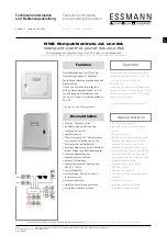


6
Description of operating
Closing with wind/rain detector
If a wind/rain detector or a rain sensor is connected, the windows
close automatically in case of beginning winds and/or rainfall,
“Ventilation Open” display flashes, vent switch out of order, the
windows close immediately in case of power or battery failure.
Note:
The ventilation function is out of order or locked in
case of power or battery failure or SHE activation in order to save
battery power.
Possible connections
- linear drives 24 V DC with integrated electronic power cut-off
or
- chain motors 24 V DC with limit switches
- overall power consumption of all motors connected: max. 4 A or
8 A depending on control panel
- 10 SHE manual call points RBH/3A... (line termination via
enclosed end resistance)
- 10 automatic detectors with 2-wire-technology, optical smoke
detectors and/or detectors of heat differential and/or detectors
of maximum heat
- 10 external ventilation switches “open”/”stop”/”closed” (e.g. type
LTA 25) per ventilation group, max. two ventilation groups
- power supply 24 V DC - 100 mA: for one wind/rain detector
WRM 24V or one rain detector RM
- 1 connection for potential-free signal: SHE activated and
malfunction and transmission of wind / rain message; contact
load 30 V / max. 2 A
* MK = motor circuit
** The functions depend on the firmware of the control panel and
the range of the PC configuration software.
Funktionsbeschreibung
Schließen mit Wind-/Regenmelder
Ist ein Wind-/Regenmelder oder Regensensor angeschlossen,
schließen die Fenster bei einsetzendem Wind und/oder Regen
selbständig. Die Anzeige “Lüftung Auf” in der Steuerzentrale blinkt,
die Lüftungsfunktion ist außer Betrieb. Bei Netz- oder Akkuausfall
schließen die Fenster sofort.
Hinweis:
Bei Ausfall der Netz- oder Akkuspannung oder bei
RWA-Auslösung ist die Lüftungsfunktion aus Gründen der Akku
-
schonung außer Betrieb bzw. gesperrt.
Anschlussmöglichkeiten
- 24 V DC Linearantriebe mit eigener elektron. Lastabschaltung
oder
- 24 V DC Kettenantriebe mit Endschaltern
- gesamte Stromaufnahme aller angeschlossenen Antriebe
max. 4 A bzw. 8 A je nach Zentralentyp
- 10 RWA-Bedienstellen RBH/3A... (Linienabschluss über
beiliegenden Endwiderstand)
- 10 automatische Melder in 2-Leiter-Technik, optische Rauch-
melder und/oder Wärmedifferential-Melder und/oder Wärme-
maximal-Melder (Linienabschluss mit aktivem Endmodul)
- 10 externe Lüftungstaster AUF/STOP/ZU (z. B.: Typ LTA 25)
je Lüftungsgruppe, max. zwei Lüftungsgruppen
- Spannungsversorgung 24 V DC - 100 mA für einen Wind-/Regen
melder WRM 24V oder einen Regenmelder RM
- je 1 Anschluss für potentialfreie Meldung RWA ausgelöst und
Störung sowie Weiterleitung der Meldung Wind /Regen;
Kontaktbelastung 30 V / max. 2 A
* MK = Motorkreis
** Die Funktionen sind abhängig von der Firmware der Zentrale
und dem Umfang der PC Konfigurationssoftware.
12V
230 V DC
=
M1
=
STOP
Lüftung/VENT
Rauchabzug
Smoke heat extraction
STOP
Lüftung/VENT
!
po
t.-
fre
ie
r E
in
ga
ng
**
po
te
ni
al
fre
e
in
pu
t*
*
PC Schnittstelle
Service Port
DIP-Schalter
DiP-Switch
11
10
1 2
3
4
12
7
6
9
5
8
O
N
OK
!
LED-Anzeigen
LED display
Taster “RWA-ZU”, Reset
“,
Switch “SHE closed
reset
Reset
Akkuanschluss
Battery connection
12V
Sicherung Akku
Fuse battery
M2
M
ot
or
1
M
ot
or
2
Sicherung
Fuse
=
M1
=
M2
Sicherung
Fuse
an
al
og
er
E
in
g
.*
*
an
al
og
in
p
ut
**
+ -


