ESD CAN-CBX-CPU5201 Скачать руководство пользователя страница 3

Document file:

I:\Texte\Doku\MANUALS\CAN\CBX\CPU5201\Englisch\CAN-CBX-CPU5201_Manual_en_15.odt

Date of print:

2014-12-22

Document type 
number:

DOC0800

Hardware version:

 CAN-CBX-CPU5201 Rev. 1.0
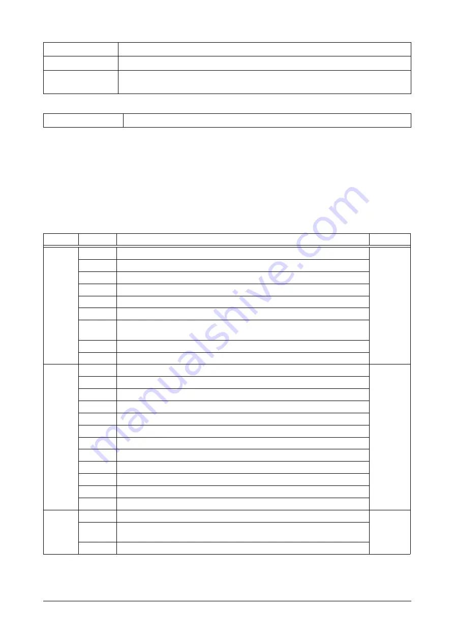
Document History

The changes in the document listed below affect changes in the hardware as well as changes in
the description of the facts, only.

Revision

Chapter

Changes versus previous version

Date

1.3

-

Trademark Notices and Safety Instructions supplemented

2012-04-16

1.1

USB interface is high-speed

2.4.2.2

Note corrected

3.2

Dimensions: hight and depth corrected

3.4

USB interface is full-speed 

4.2.1

Shield connected to FE

4.4

Signal description: double listing of signal names removed, Shield connected to
FE

4.6.1

Shield connected to FE

8.

Order information corrected

1.4

2.1

Reference to chapter “Conductor Connection/Conductor Cross Sections“ inserted

2013-09-06

2.3.1

Reference to chapter “Appendix CAN-CBX-CPU5201-PLC“ inserted

2.4

Chapter “Starting-Up“ ne

3.9

Module CAN-CBX-CPU5201/DP QNX inserted

3.10

Software support revised, license information new

4.1, 4.2.1 Note inserted

4.4

Note about cable types inserted

4.8

Chapter “Conductor Connection/Conductor Cross Sections new

7

Chapter: „Appendix CAN-CBX-CPU5201-PLC” new

8

Chapter: „References” new

9

Former chapter 7., moved to chapter 9, Declaration of Conformity new

10

Former chapter 8., moved to chapter 10, order information revised

1.5

-

'Data Safety' notice and Typographical Conventions inserted 

2014-12-22

2.4, 7.1

Sentence concerning termination devices in step 2 deleted, cross-reference to
chapter '' (page 38) inserted

9.

Declaration of conformity updated 

Technical details are subject to change without further notice.

CAN-CBX-CPU5201

Hardware Manual • Doc. No.: C.3071.21 / Rev. 1.5

Page 3 of 53

Содержание CAN-CBX-CPU5201

Страница 1: ...al to Product C 3071 02 C 3071 03 C 3071 04 C 3071 05 C 3071 06 CAN CBX CPU5201 Hardware Manual Doc No C 3071 21 Rev 1 5 Page 1 of 53 esd electronic system design gmbh Vahrenwalder Str 207 30165 Hanno...

Страница 2: ...tion of this document in any form whole or in part are subject to esd s written approval 2014 esd electronic system design gmbh Hannover esd electronic system design gmbh Vahrenwalder Str 207 30165 Ha...

Страница 3: ...4 2 1 Reference to chapter Conductor Connection Conductor Cross Sections inserted 2013 09 06 2 3 1 Reference to chapter Appendix CAN CBX CPU5201 PLC inserted 2 4 Chapter Starting Up new 3 9 Module CA...

Страница 4: ...neering Conformity The CAN CBX CPU5201 is an industrial product and meets the demands of the EU regulations and EMC standards printed in the conformity declaration at the end of this manual Warning In...

Страница 5: ...3 5 2 CAN2 22 3 6 Ethernet Interface 22 3 7 Serial Interface 23 3 8 Real Time Clock RTC 23 3 9 Profibus DP Interface Option 23 3 10 Software Support 24 3 11 Power PC Microcontroller MPC5121 25 3 11 1...

Страница 6: ...Applications Two Wire 44 5 6 2 Cable for heavy industrial Environment Applications Four Wire 44 6 CAN Troubleshooting Guide 45 6 1 Termination 45 6 2 Electrical Grounding 46 6 3 Short Circuit in CAN...

Страница 7: ...cautions to tell you about operations which might have unwanted side effects Note Notes to point out something important or useful Number Representation All numbers in this document are base 10 unles...

Страница 8: ...e via an RJ45 plug in the front An USB device e g memory stick can be connected on the front side USB 2 0 Host interface running with high speed 480 MBit s Two serial RS 232 interfaces Rx Tx signals a...

Страница 9: ...m Fig 2 Connecting diagram of CAN CBX CPU5201 DP Note See also page 26 ff for signal assignment of the CAN connectors For information about conductor connection conductor cross sections see page 37 CA...

Страница 10: ...g for the Profibus DP address is only determined at the moment the module is powered on The operating system BSPs Board Support Packages which are currently available support functions for reading the...

Страница 11: ...ransmission of CAN data off no data transmission P Error on firmware update error off D User specific off User specific CAN CBX CPU5201 always off optional on only at CAN CBX CPU5201 DP Option Profibu...

Страница 12: ...net data packets yellow Table 2 Indication of the Ethernet LEDs 2 3 1 1 Assignment of LED Labelling to Name in the Schematic Diagram Labelling on the CAN CBX CPU5201 Name in Schematic Diagram C LED 14...

Страница 13: ...bus has to be terminated at both ends esd offers special T connectors and termination connectors Additionally the CAN_GND signal has to be connected to earth at exactly one point in the CAN network Re...

Страница 14: ...CBX station via the 24V connector A feed through of the 24 V power supply voltage can cause damage on the CBX modules Figure 5 CAN CBX station Earthing the mounting rail Note Connect the mounting rail...

Страница 15: ...mmunication and power signals in parallel with one The bus connectors can be plugged together before or after mounting the CAN CBX modules One mounting rail bus connector is included in delivery Funct...

Страница 16: ...Bus via the bus connector Connect the bus connectors and the InRailBus if not already done Figure 8 Mounted CAN CBX module Figure 9 Wiring diagram with CAN CBX CPU5201 as bus master Page 16 of 53 Hard...

Страница 17: ...separately see order information Figure 10 Mounting rail with InRailBus and terminal plug Plug the terminal plug into the socket on the right of the mounting rail bus connector of the InRailBus as de...

Страница 18: ...e InRailBus is terminated via two internal resistors each 33 in the CAN CBX CPU5201 module The bus length of the InRailBus shall not exceed l 0 3 m Figure 11 Connecting the CAN signals to the CAN CBX...

Страница 19: ...ry change every 2 5 3 years is recommended 2 6 1 Battery Change The battery is inside the case of the CAN CBX CPU5201 module For a battery change the case has to be opened Attention The battery change...

Страница 20: ...2 and power supply via InRailBus RJ12 socket X1100 Serial interface RJ45 socket X1200 Ethernet interface Only for factory test and programming purposes internal X700 16 pin SMD socket strip Optional i...

Страница 21: ...3 CPU Unit CPU PowerPC MPC5121 with FPU 400 MHz DDR2 SDRAM 512 Mbyte Flash NAND 1 Gbyte EEPROM 32 Kbyte Hardware Watchdog CPU internal time adjustable by user from 50 ms up to 65535 ms in steps of 1 m...

Страница 22: ...N 2 0 Electrical isolation none Physical Layer according to ISO 11898 2 transfer rate up to 1 Mbit s Bus termination internal 66 no additional terminating resistor for the InRailBus necessary if the l...

Страница 23: ...etime 2 5 3 years The battery lifetime strongly depends on the environmental influences Therefore an regular battery change every 2 5 3 years is recommended Table 11 RTC with battery 3 9 Profibus DP I...

Страница 24: ...CPU5201 Linux CAN CBX CPU5201 DP Linux and CAN CBX CPU5201 PLC the module supports Linux operating systems Modules CAN CBX CPU5201 Linux order no C 3071 02 CAN CBX CPU5201 DP Linux order no C 3071 03...

Страница 25: ...0 0x3001 FFFF SRAM 128 KB 0x8000 0000 0x803F FFFF IMMR 4 MB 0x8200 0000 0x8200 FFFF VPC3 64 KB CAN CBX CPU5201 DP only 0xFFC0 0000 0xFFFF FFFF NOR Boot FLASH 64 MB 3 11 3 Interrupt Assignment The inte...

Страница 26: ...and conductor cross section see page 37 Pin Position Pin Assignment Labelling on the CAN CBX CPU5201 24 V M P Labelling on the connector Pin 1 2 3 4 Signal Do not connect Do not connect M24 GND P24 24...

Страница 27: ...ter Figure 12 CAN1 interface CAN CBX CPU5201 Hardware Manual Doc No C 3071 21 Rev 1 5 Page 27 of 53 VIB VOA GND1 VOB VIA VDD2 GND2 VDD TX R GND BUSL RX BUSH L H 5V 5V CAN0_GND DC DC 2 4 GND 5V 5 V G 1...

Страница 28: ...tion CAN1_L CAN1_H CAN1 signals CAN1_GND reference potential of the local CAN1 physical layer Shield pin for line shield connection using hat rail mounting direct contact to the mounting rail potentia...

Страница 29: ...r Assignment Connector type Mounting rail bus connector CAN CBX TBUS Phoenix Contact ME 22 5 TBUS 1 5 5 ST 3 81 KMGY Connector View Pin Assignment Pin Signal 5 M24 GND 4 P24 24 V 3 CAN2_GND 2 CAN2_L 1...

Страница 30: ...eive Data 7 8 S Shield Signal Description MDI0 MDI1 EtherCAT data lines reserved for future applications do not connect Shield case shield connected to earth potential FE Note Permissible cable types...

Страница 31: ...of the interface support bit rates up to 115 2 kbit s 4 5 3 Connection of the Serial Interface The figures below explain the short terms of the signals used in the connector assignment The signal nam...

Страница 32: ...the version with DP option CAN CBX CPU5201 DP Figure 14 1x RS 232 1x RS 485 via RJ12 socket Page 32 of 53 Hardware Manual Doc No C 3071 21 Rev 1 5 CAN CBX CPU5201 TxD_S1 GND RxD_S1 1 4 6 Pin number o...

Страница 33: ...Pin Position Pin Standard 2x RS 232 Option 1x RS 232 1x RS 485 CAN CBX CPU5201 DP only Signal Signal 1 GND Rx Tx _S1 RS 485 COM2 2 Tx_S0 RS 232 COM1 Tx_S0 RS 232 COM1 3 Rx_S0 RS 232 COM1 Rx_S0 RS 232...

Страница 34: ...Profibus DP interface is only equipped on the modules CAN CBX CPU5201 DP Linux esd order no C 3071 03 and CAN CBX CPU5201 DP QNX esd order no C 3071 06 Figure 15 Position of the Profibus DP interface...

Страница 35: ...t P5V 6 1 The connector case is connected to earth potential FE Signal description A RxD TxD P B RxD TxD N receive and transmit data CNTR P control signal for Repeater Request To Send P5V power supply...

Страница 36: ...iagram Labelling on CAN CBX CPU5201 Name in schematic diagram 24V X100 USB X1010 COM1 2 X1100 ETH X1200 CAN X1300 Profibus DP CAN CBX CPU5201 DP only X1000 The schematic diagram is not part of this ma...

Страница 37: ...5 mm 0 25 mm Conductor cross section stranded with ferrule with plastic sleeve max 2 5 mm 0 5 mm Conductor cross section AWG kcmil min 24 26 Conductor cross section AWG kcmil max 12 16 2 conductors wi...

Страница 38: ...loss across the complete system and cabling parasitic loadings network imbalances ground offsets against earth potential and signal integrity Therefore the practical maximum number of nodes bus lengt...

Страница 39: ...has to be connected to the functional earth FE at exactly one point 4 A CAN net must not branch exception short cable stubs and has to be terminated with the characteristic impedance of the line gene...

Страница 40: ...contacts gender changer are available from esd order no C 1303 01 DSUB termination connectors with male contacts order no C 1302 01 or female contacts order no C 1301 01 and additional functional eart...

Страница 41: ...as to be terminated with the characteristic impedance of the line generally 120 10 at both ends between the signals CAN_L and CAN_H and not to CAN_GND 5 Keep cable stubs as short as possible l 0 3 m 6...

Страница 42: ...n instead of an external CAN termination plug 9 pin DSUB termination connectors with integrated termination resistor and male and female contacts gender changer are available from esd order no C 1303...

Страница 43: ...l values of reachable wire length with esd interface lmax m CiA recommendations 07 95 for reachable wire lengths lmin m 1000 800 666 6 500 333 3 250 166 125 100 83 3 66 6 50 33 3 20 12 5 10 37 59 80 1...

Страница 44: ...rmany www concab de e g BUS PVC C 1x 2x 0 22 mm Order No 93 022 016 UL appr BUS Schleppflex PUR C 1x 2x 0 25 mm Order No 94 025 016 UL appr 5 6 2 Cable for heavy industrial Environment Applications Fo...

Страница 45: ...esistance of the CAN data pair conductors and the attached terminating resistors To test it please 1 Turn off all power supplies of the attached CAN nodes 2 Measure the DC resistance between CAN_H and...

Страница 46: ...ata if there is a short circuit between CAN_GND and CAN_L but generally the error rate will increase strongly Make sure that there is no short circuit between CAN_GND and CAN_L 6 4 CAN_H CAN_L Voltage...

Страница 47: ...see figure below 2 Measure the DC resistance between CAN_H and CAN_GND see figure below 3 Measure the DC resistance between CAN_L and CAN_GND see figure below The measured resistance has to be about...

Страница 48: ...ation connectors Additionally the CAN_GND signal has to be connected to earth at exactly one point in the CAN network Refer to chapter page 38 for further information A CAN participant with a CAN inte...

Страница 49: ...ndow you can change the parameters via a double click Activate Reset Device now and then click Apply Changes Enter the device password Default password plc_1975 The CAN CBX CPU5201 PLC reboots and wil...

Страница 50: ...ess of the CAN CBX CPU5201 PLC see above in the target settings of the CODESYS programming environment 7 2 3 Indication of the CAN CBX CPU5201 PLC LEDs The position of the LEDs is described in Figure...

Страница 51: ...d circuit board connector FKCT 2 5 4 ST KMGY 1921900 downloaded 2012 11 21 2 Phoenix Contact GmbH Co KG Blomberg Technical data is taken from COMBICON Online Catalog http www phoenixcontact com assets...

Страница 52: ...Declaration of Conformity 9 Declaration of Conformity Page 52 of 53 Hardware Manual Doc No C 3071 21 Rev 1 5 CAN CBX CPU5201...

Страница 53: ...nRailBus for the connection of the 24V power supply voltage and the CAN interface Female type C 3000 02 CAN CBX TBUS Connection adapter Terminal plug of the CBX InRailBus for the connection of the 24V...

Отзывы: