


Hardware Installation
2.5.2.2 Connection of CAN1 and CAN2
Note:
Differing from the other
CAN-CBX-I/O
modules the
CAN-CBX-CPU5201
module
comes with two independent CAN interfaces.
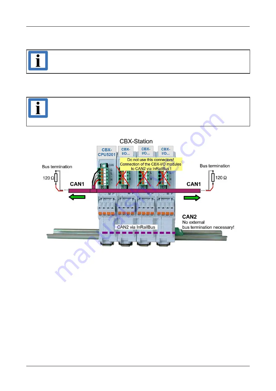
CAN net 2 of the CAN-CBX-CPU5201 is connected to the CAN-CBX-I/O modules via InRailBus as
described in the wiring diagram (figure 9).
Note:
It is important to use the terminating resistors in the correct way! See also figure 11.
The InRailBus is terminated via two internal resistors (each 33 Ω) in the CAN-CBX-
CPU5201 module. The bus length of the InRailBus shall not exceed l = 0,3 m.
Figure 11:
Connecting the CAN signals to the CAN-CBX station
2.5.3 Remove the CAN-CBX Module from InRailBus
If the CAN-CBX module is connected to the InRailBus please proceed as follows:
Release the module from the mounting rail in moving the foot catch (see Fig. 8) downwards (e.g.
with a screwdriver). Now the module is detached from the bottom edge of the mounting rail and
can be removed.
Page 18 of 53
Hardware Manual • Doc. No.: C.3071.21 / Rev. 1.5
CAN-CBX-CPU5201


