


Page Mode
CAN-CBM-DP
Software Manual Rev. 2.0
51
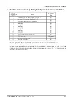
6.4.6 Rx-Configuration via Pages 151...250
The Rx-identifiers are configured via pages 151 to 250 (decimal). The page structure is as follows:
Byte
0
1
2
3
4
5
6
7
8
9
10
11
12
13
14
15
16
17
18
19
20
...
Length
[bytes]
2
6
4
1
1
4
1
1
...
Contents
page no.
protocol data
RxId_value
form
length
RxId_value
form
length
...
parameters of Rx-identifier 1
parameters of Rx-identifier 2
Example
t
151
...
301
B8
6
303
B8
8
...
Table 6.4.5:
Structure of pages 151...250
Bytes 0 to 7 contain the protocol information already mentioned above (refer also to page 48).
From byte 8 in the first segment (byte 2 in the following segments) the definition of the desired Rx-
identifiers is transmitted to the CAN gateway. For each Rx-identifier 6 bytes are required:
RxId_value
These four bytes specify the numeric value of the Rx-identifier.
The CAN-CBM-DP module with the order-no. C.2844.03 supports 11-bit-identifier:
0 ... 2047 (decimal).
The CAN-CBM-DP module with the order-no. C.2844.05 supports 29-bit-identifier, too.
form
Via this byte you can choose whether the output data is to be converted from Motorola
data format of the PLC into Intel data format of the CAN network or not. Byte
form
has
already been described in detail on page 29.
length
Here the number of data bytes of the Rx-identifier is specified. Entries between 1 and
8 are permissible.


