


16
The MigMaster 300i is capable of MIG, TIG, and STICK
welding processes. It is designed to connect and dis-
connect a MIG Torch, TIG Torch, and a STICK elec-
trode holder quickly and safely.
As shown in Figure 4-3, the MigMaster 300i has posi-
tive (J5) and negative (J6) ELECTRODE output recep-
tacles for output power.
The torch polarity cable is hardwired internally to torch
connector receptacle J4 (located in wire feed compart-
ment). This internal connection and the ELECTRODE
receptacle (- or +) that the torch polarity cable plug
(P12) is connected to, determine the welding polarity.
For example; by connecting P12 to the negative (-)
ELECTRODE output receptacle (J6), the torch con-
nected at J4 will be welding with straight dc polarity.
By connecting P12 to the positive (+) ELECTRODE
output receptacle (J5), the torch will be welding with
reverse dc polarity. The latter polarity (reverse) is the
most commonly used way to weld with the MIG pro-
cess.
4.5 WELDING CABLE CONNECTIONS (WORK
CABLE)
Connect the plug of the work cable to the ELECTRODE
output connector not being used. Connect the work
clamp solidly to the workpiece on work table. Clamp
onto a bare metal area.
A GOOD ELECTRICAL CONNECTION TO THE
WORK IS ESSENTIAL TO PROPER WELDING OP-
ERATION AND TO PREVENT ELECTRIC SHOCK.
Welding cables should be kept as short as possible
and be of adequate current carrying capacity. Resis-
tance of the welding cables and connections causes a
voltage drop which is added to the voltage drop of the
arc. Excessive cable resistance may result in a re-
direction of the maximum usable current output of the
equipment.
The proper operation of this equipment is to a large
extent dependent on the use of welding cables and
connections which are in good condition and of ad-
equate size.
4.6 INSTALLATION FOR MIG WELDING
BE SURE THE BRANCH CIRCUIT OR MAIN DIS-
CONNECT SWITCH AND MIGMASTER POWER
SWITCH (FIGURE 4-3) IS OFF OR ELECTRICAL
INPUT CIRCUIT FUSES ARE REMOVED BEFORE
MAKING OR CHANGING SECONDARY CONNEC-
TIONS ON THE MIGMASTER 300i. BE SURE THAT
WIRE AND/OR TORCH IS NOT TOUCHING
WORKPIECE WHEN INITIALLY APPLYING POWER.
4.6.1 TORCH CONNECTION (MT-200CC)
The MT-200cc Torch is supplied as standard equip-
ment with the MigMaster 300i Power Source.
To connect the MT-200cc Torch to the Power Source,
line up the connector of the torch cable with matching
holes in Power Source connector receptacle J4 (Fig-
ure 4-3). Insert torch cable plug and tighten the lock-
ing collar.
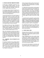
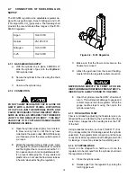
4.6.2 TORCH POLARITY CABLE AND WORK
CABLE (FIGURE 4-4)
For welding mild steel, stainless steel, and aluminum
using cored wires, connect plug P12 to the ELEC-
TRODE positive (+) output receptacle (J5) on Power
Source. Connect the work cable plug to the ELEC-
TRODE negative (-) output receptacle (J6) as described
in paragraph 4.5. The connection setup described will
give dc reverse polarity welding. In addition to Figure
4-4, refer to the MIG connection illustration on the front
of the Power Source in the MIG block.
Figure 4-4. MIG Connections
For some cored wires the torch needs to be connected
for straight dc polarity welding. To make this connec-
tion setup, connect plug P12 to the ELECTRODE nega-
tive (-) output receptacle (J6) and the work cable plug
to the ELECTRODE positive (+) output receptacle (J5)
as described in paragraph 4.5. After making the de-
sired polarity welding connections, place Process Se-
lector Switch (Figure 4-3) to the MIG position. Refer to
Section V for operational instructions.
J6
P12
J5
J6
P12
J5
Содержание Migmaster 300i cvcc
Страница 38: ...38...
Страница 39: ...39...
Страница 40: ...40...
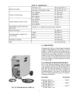
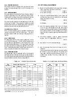
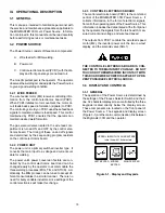
Страница 46: ...46 2 3 4 5 6 7 8 9 10 11 12 13 14 15 1 16 17 18 19 20 21 FIGURE 8 3 MIGMASTER 300i RIGHT INTERIOR VIEW...


