14
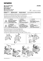
Ensure proper insertion of “11B” wire by pulling the wire by hand and the wire
Should not come off the terminal.
5. Push the boot of “11B” wire to completely cover the crimp.
Same procedure in reverse is to be followed to change from 5A to 1A .
5.2. Human Machine Interface (HMI)
The user friendly HMI provided on the front panel has following features:
Six digit, 7 segment LED display (First two digits are Red colour and other four digits are
Green colour). First two digits (Red) displays the main menu or type of fault when
selected for Setting mode or Trip indication respectively. Remaining four digits (Green)
displays Sub menu or "Trip" indication respectively.
2. Green LED
- Protection healthy indication
3. Yellow LED (STARTER)
- Starter indication
4. Red LED (TRIP)
- Trip indication,
5. Red LED (in
→
Key)
- Sub Menu
6.
↑
Key
- Up scrolling
7.
↓
Key
- Down scrolling
8.
×
Key
- Enter / Reset / Cancel / To check Version
5.3. How to operate HMI
Remove the front cover by unscrewing the four knurling screws.
Apply DC supply. Terminals 22,24 and 23 are for positive, negative and earth respectively
as per relay rating. When the relay powers up it takes few seconds to complete the self-
check routing.
Ensure Protection Healthy LED (Green) is ON and
indication appears on the
LED display unit. Wait until the
indication goes off.
Press
↑
or
↓
key
is displayed
Represents MIT 161 relay
Press
↓
key repeatedly scrolls down the Factory setting Main menu in the following order
on the display.
-
Earth fault is OFF (
is Main menu and
is sub menu)
-
Lowset is OFF


