background image


MI_STAR_EN.doc


SR Installation Manual EN 

Indice : C 

03/05/2019 


5 / 15


ERECA SAS  75 rue d'Orgemont, 95210 SAINT GRATIEN France 

Tel +33 1 39 89 76 23    www.ereca.fr 


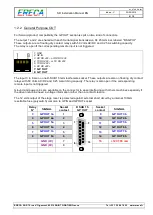
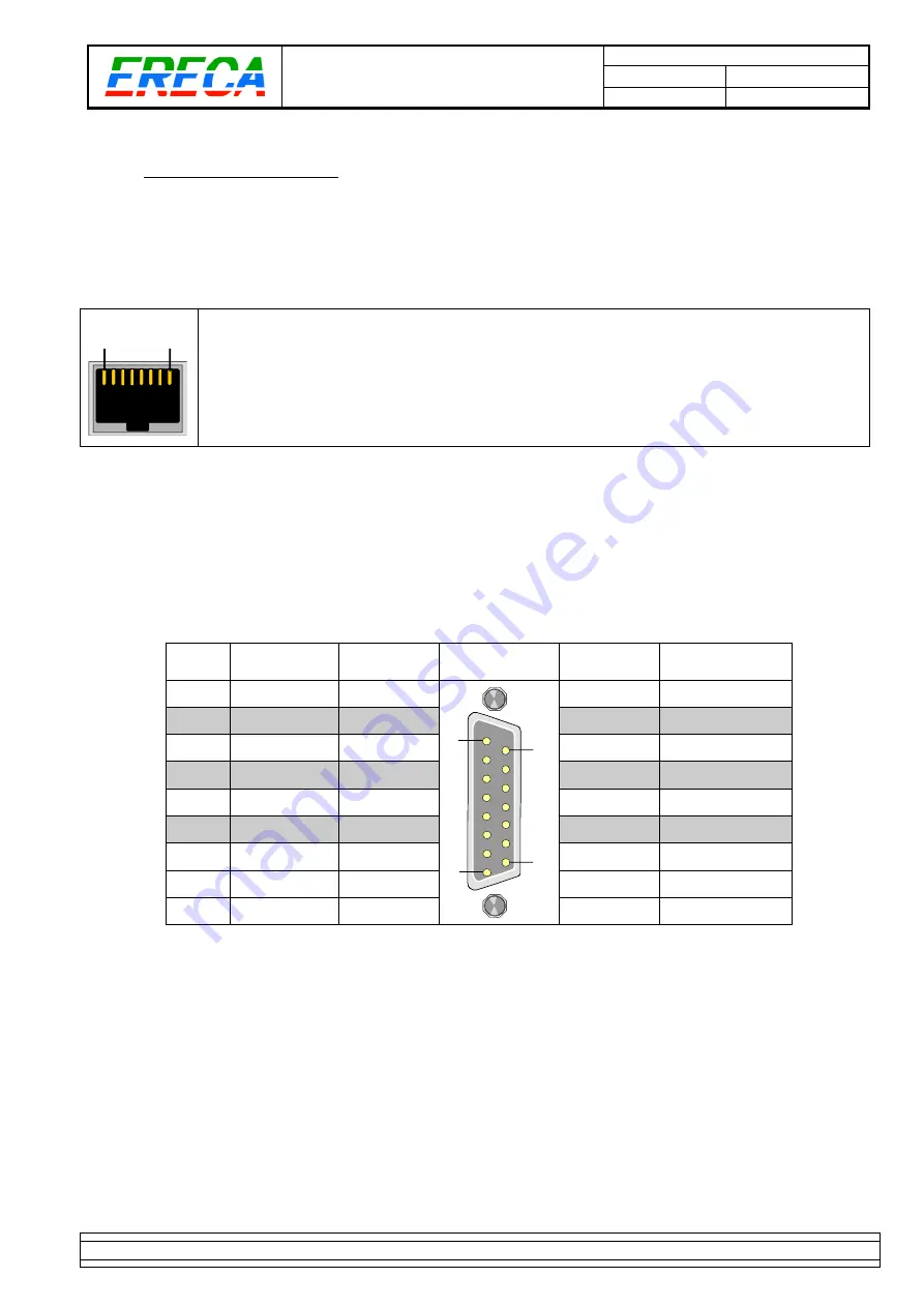
1.2.2  General Purpose OUT 

 
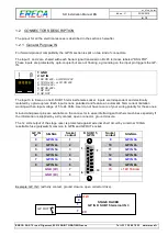
For forward product compatibility the GP OUT section is split on two kind of connectors. 
 
The output 1 and 2 are shared with each Serial signal transmission RJ 45 terminal, labeled "RS GPIO". 
These outputs are on floating dry contact relays with 50 Volts AC/DC and 0.25 A switching capacity. 
The relay is open if the corresponding remote input is not triggered.  
 

1

8


1: GND 
2: GP IN 
3: RX RS 422 

– or RX RS 232 

4: TX RS 422 

– or TX RS 232 

5: TX RS 422 + 
6: RX RS 422 + 

7: GP OUT 
8: GP OUT


The input 3 to 8 are on one D-SUB 15 terminal female socket. These outputs are also on floating dry contact 
relays with 50 Volts AC/DC and 0.25 A switching capacity. The relay is also open if the corresponding 
remote input is not triggered. 
 
Ground and power pins are available on the connector to ease interfacing with others machines especially if 
the driven machine need a voltage information rather than a contact closure. 
 
The 12 volts output of the stage racer is protected against external short circuit by a internal 100mA 
resettable fuse (polyswitch) common to GPIN and GPOUT socket. 
 

Relay 

N° 

SIGNAL 

Socket 

contact 

D SUB 15 

GP OUT 

Socket 

contact 

SIGNAL 

GP OUT 3a 

1

9

8

15


GP OUT 3b 

GP OUT 4a


10 

GP OUT 4b


GP OUT 5a


11 

GP OUT 5b


GP OUT 6a


12 

GP OUT 6b


GP OUT 7a


13 

GP OUT 7b


GP OUT 8a


14 

GP OUT 8b


GND (0V) 

15 

+ 12V 100 mA 


GND (0V) 


Содержание Stage Racer

Страница 1: ...MI_STAR_EN doc SR Installation Manual EN Indice C 03 05 2019 1 15 ERECA SAS 75 rue d Orgemont 95210 SAINT GRATIEN France Tel 33 1 39 89 76 23 www ereca fr ...

Страница 2: ...nalog AUDIO 6 1 2 4 Digital AUDIO 7 1 2 5 Serial ports 8 1 2 6 Ethernet ports 8 1 2 7 HD VIDEO ports 9 1 2 8 Composite VIDEO ports 9 1 2 9 OPTICAL access 9 1 3 Optional Connectors Fuse Part number 10 1 3 1 Description Error Bookmark not defined 1 3 2 12 RS422 Pinout Error Bookmark not defined 1 4 SUPERVISION 12 1 4 1 Password Default 12 1 4 2 IP address 12 2 TECHNICAL SPECIFICATIONS 13 3 APPENDIX ...

Страница 3: ...er 1 1 CONNECTORS LOCATION The stage racer provides on one side all the connection of the base module signals Some optional connectors are located on the front face close to the LED display panel Connectors for each signal are described below D SUB 15 female sockets for GPIO 3 8 D SUB 37 female sockets for analog audio RJ 45 for Serial signals GPIO 1 2 Ethernet BNC for PAL HD SDI and AES LEMO 3K N...

Страница 4: ...ndent and electrically isolated by opto couplers Each input is none polarized and feature an automatic 5mA current limitation working with an input voltage of 5 to 24 Volts User do not have to care of your wiring polarity for these ones Ground and power pins are available on the connector to ease interfacing with others machines especially if the information is supplied by a dry contact open conne...

Страница 5: ... input 3 to 8 are on one D SUB 15 terminal female socket These outputs are also on floating dry contact relays with 50 Volts AC DC and 0 25 A switching capacity The relay is also open if the corresponding remote input is not triggered Ground and power pins are available on the connector to ease interfacing with others machines especially if the driven machine need a voltage information rather than...

Страница 6: ...IO 11 AUDIO 12 14 33 AUDIO 12 AUDIO 13 15 34 AUDIO 13 AUDIO 14 16 35 AUDIO 14 AUDIO 15 17 36 AUDIO 15 GND 18 AUDIO 16 19 37 AUDIO 16 1 2 3 2 Audio option location For units equipped with the 8 microphones gain block the gain block is installed in the RX unit The gain blocks are connected to channels 8 to 16 Thru the web server each 8 to 16 input can be amplified with a gain ranging from 9 to 60 dB...

Страница 7: ...Ohms Note2 The bidirectional function of the device constraint the design specially to provide an accurate AES activity led display and avoid signal loop if port impedance is not 75 ohms The internal FPGA seeks for AES3 audio XYZ preamble at 48 KHz to light the corresponding AES Led and enable transmission in this direction Basically the equipment is able to transmit 44 1 and 48 KHz audio in the o...

Страница 8: ...2 Stage racer electrical INPUT 5 TX RS 422 Stage racer electrical INPUT 6 RX RS 422 Stage racer electrical OUTPUT 7 GP OUT 8 GP OUT Note For RS 485 Telex RTS talkback panels please ask ERECA for wiring tip 1 2 5 2 RS232 Refer The RS 232 signal ground to pin 1 Leave pins 5 and 6 unconnected 1 8 1 GND Ground ref Shield 2 GP IN 3 RX RS 232 Stage racer electrical OUTPUT 4 TX RS 232 Stage racer electri...

Страница 9: ... provided for this signal often use as Genlock 1 2 9 OPTICAL access 1 2 9 1 Standard The stage racer uses only two fibers for signals transmission The STAGE RACER is available with the following optical terminals LEMO 3K NEUTRIK OPTICALCON Duo NEUTRIK OPTICALCON Quad SC APC SC PC ST PC LC For OpticalCon QUAD connectors the 2 remaining fibers are output on 2 SC APC connectors located on the front f...

Страница 10: ...RACER is composed of 1 STAR TX 1 STAR RX 1 2 3 4 5 6 1 3 2 12 RS422 Pinout One D SUB 25 pin female socket provide the access to the extra RS422 channels 1 to 6 One D SUB 25 pin female socket provide the access to the extra RS422 channels 7 to 12 Channel SIGNAL Socket contact D SUB 25 RS422 1to6 RS422 7to12 Socket contact SIGNAL 1 and 7 IN 1 7 1 1 25 14 13 14 IN 1 7 1 and 7 OUT 1 7 2 15 OUT 1 7 2 a...

Страница 11: ...rnally for optimum compatibility with transmitted protocols If impedance matching is needed a small SFR16 resistor could be added directly on the D SUB pints together with the signal wire The 12 extra RX 422 supported datarate of each signal is about 25Kbds This option is totally independent and do not affect the 2 standard serial interfaces Note For RS 485 Telex RTS talkback panels please ask ERE...

Страница 12: ... the front face for 5 seconds the unit will revert to default settings 1 4 2 IP address Setup the IP address of the unit after validation with the password the unit instantaneously switches to the new IP settings an internet link route the user to the new address Default IP 192 168 1 245 on a TX 192 168 1 246 on a RX NetMask 255 255 254 0 Further information is available in the Stage Racer Technic...

Страница 13: ...tor 16 bidirectional channels Rugged box 4 on XLR 4 on one SUB D 25 socket for 1U rack all on SUB D 37 Impedance Input 10 KΩ differential non floating Output 20 Ω differential non floating Amplitude 4 dBm nominal saturation at 18 dBm Bandwidth 50 Hz to 15 KHz at 0 5dB 20 Hz to 20 KHz at 3 dB Distortion 0 05 at 1Khz 18 dBm Signal to noise ratio 90dB A weighted Digital audio Number connector 4 AES b...

Страница 14: ...orted trough the web server Settings All settings are done trough the web server Optical OPTION Redundant path Double optical transmission with automatic optical path selection Optical losses 1 8 dB per link for optical switching Analog Audio OPTION Input Microphone input gain block on 8 of the 16 channels Mic input Gain From 10 to 60 dB Bypass and Tunable by 3 dB steps through internal Web Server...

Страница 15: ...MI_STAR_EN doc SR Installation Manual EN Indice C 03 05 2019 15 15 ERECA SAS 75 rue d Orgemont 95210 SAINT GRATIEN France Tel 33 1 39 89 76 23 www ereca fr 3 APPENDIX CAD FILE DOCUMENT ...

Отзывы: